3 connecting the frame and reference grounds – Alpha Technologies Cordex CXPS-M 48_24-1200_600A User Manual
Page 42
9400004-J0 Rev B
40
6.3 Connecting the Frame and Reference Grounds
CAUTION!
The grounding methods described in this section are generic. Follow local requirements
and electrical code.
NOTE:
This power system is suitable for installation as part of a Common Bonding Network
(CBN) and is intended to be used in a DC-C configuration (common DC return).
A true single point ground system means that everything is referenced to a single point that is tied to the external
earth ground system. In reality each component and external source is effectively bonded to a single point, which
is then effectively bonded to the facility or site external ground system.
6.3.1 Connecting the power plant battery return reference lead
1. Connect the isolated power system battery return bus (BRB) to the building master ground bus (MGB) or
floor ground bus (FGB) in larger buildings (Figure 23). This acts as a system reference and a low impedance
ground path for surges, transients, noise, etc. The MGB or FGB should have a direct low impedance path to
the building grounding system.
2. Size the cable between the power system and the MGB or FGB so that there is sufficient ampacity to clear
the largest fuse or breaker on the power system, excluding the battery protection fuse or circuit breaker—see
Table G on page 41. This is the minimum requirement for these high capacity plants. Other factors, including
length of cable and special grounding requirements of the load, must be factored in. The insulated cable
should be equipped with two-hole crimp type lugs and should not have any tight bends or kinks.
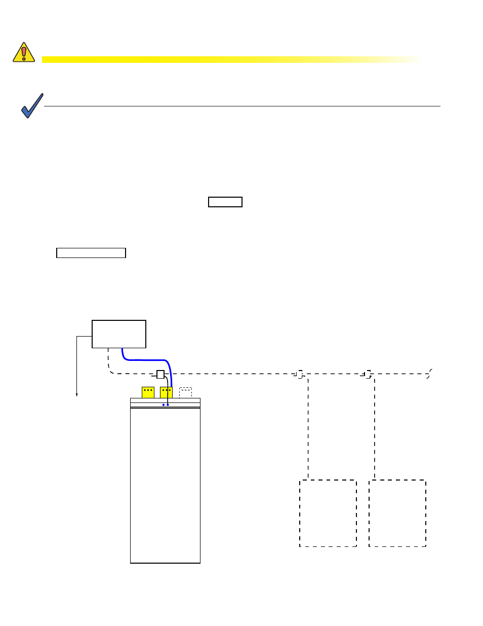
Figure 23 —
Frame and reference returns (front view)
MGB or FGB
BRB
CXPS power
system bay
Battery rack
Battery rack
Frame
ground
To site
ground
Optional external battery plant