5 battery connections, Figure 27 — battery terminations (front view) – Alpha Technologies Cordex CXPS-M 48_24-1200_600A User Manual
Page 45
43
9400004-J0 Rev B
6.5 Battery Connections
Battery cables should be sized for a 0.25 V drop from battery to the power system at full load including antici-
pated growth. The cables should also meet ampacity requirements.
6.5.1 Battery Return Connections
Procedure:
1. Connect the battery return cables to an external battery return bus bar, if installed, (Figure 26) or to the return
bus bar termination on the bay:
External Battery Return Bus Bar (Figure 26)
Battery Return Termination on the Bay (Figure 27)
• 24 sets of 1/2" holes on 1¾" centers
• 24 sets of 3/8" holes on 1" centers
• 72 sets of 1/4" holes on 3/8" centers
• 6 sets of 1/2" on 1 3/4" centers and/or
3/8" on 1" centers (12 if connected to both
sides of the bar)
Figure 26 —
External battery return bus bar (dual level shown)
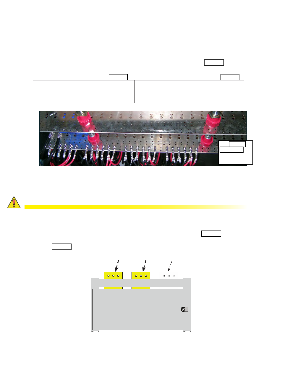
6.5.2 Hot Voltage Battery Cables
CAUTION!
Do NOT make final connection to battery live. Insulate and leave disconnected or re-
move the battery fuses. Switch battery contactors off (if used).
1. Connect "hot" primary voltage cables directly to the primary "hot" voltage bus bar (Figure 27).
2. For the dual voltage option, connect "hot" secondary voltage cables directly to the secondary "hot" voltage
bus bar (Figure 27).
recommended
torque values.
Figure 27 —
Battery terminations (front view)
Primary "hot"
"hot" secondary (dual
voltage option)
Return