Installation, 1 floor drilling for standard anchoring, Figure 18 — template for anchoring bolts – Alpha Technologies Cordex CXPS-M 48_24-1200_600A User Manual
Page 33
31
9400004-J0 Rev B
5. Installation
The power system must be mounted in a clean and dry environment. Provide sufficient free space at the front
and rear of the power system to meet the cooling requirements of the rectifiers in the power system and to allow
easy access to the power system components.
5.1 Floor drilling for standard anchoring
The anchoring kit and procedures in this section are for a sesimic installation, but apply equally well to a non-
seismic installation.
5.1.1 Drilling the holes for the anchor bolts
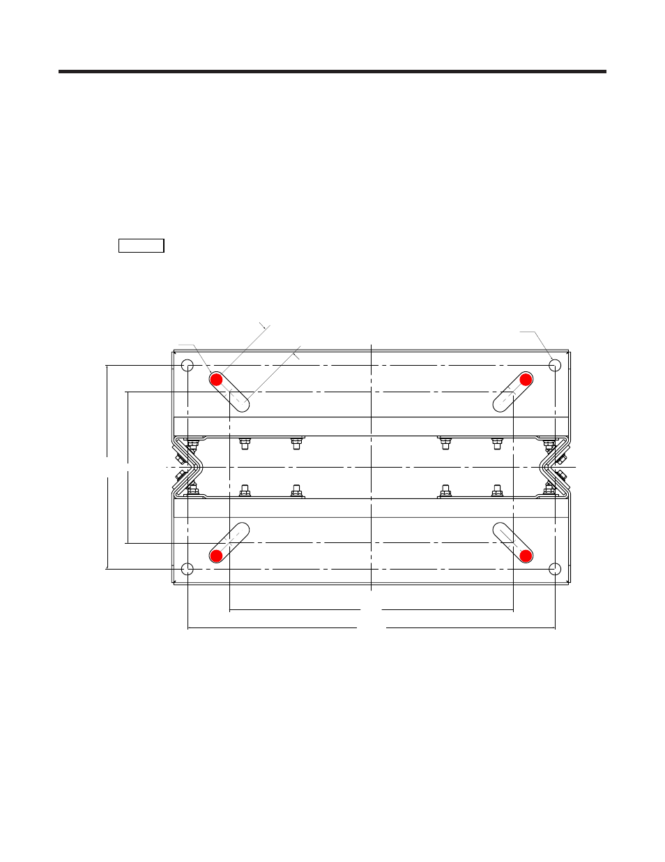
Locate bolts in
slots as shown for
greatest stability.
1. Use a rebar locator to plan for the anchor positions.
2. Refer to Figure 18 (drawing 0300047-06) to mark the four anchor hole positions for seismic anchoring.
The red dots show the preferred location for the anchor holes within the slots.
9.6
2.312 TYP
Ø0.75 TYP
Ø0.938 TYP
18.1
23.5
13.0
Figure 18 — Template for anchoring bolts