Figure 21 — temperature probe – Alpha Technologies Cordex CXPS-M 48_24-1200_600A User Manual
Page 37
35
9400004-J0 Rev B
5.4.2 Installation of External Batteries
This information is provided as a guideline and is not meant to imply that batteries are part of this power system.
Verify that all battery breakers, DC circuit breakers, and fuses on the distribution panels are either in the OFF
position or removed.
Before assembly, clean cells (where applicable) as per the battery manufacturer's recommendations. First
neutralize any acid with a baking soda and water solution. Then wipe the cells with clean water. Use a corrosion-
inhibiting agent such as NO-OX or NCP-2 on all battery terminal connections.
1. Assemble battery rack (if required) and the cells or mono-blocks as per the installation instructions supplied
with the batteries.
2. Ensure that the battery output cabling will reach the [+] and [–] terminals of the series battery string and that
the batteries are oriented correctly for easy installation of the inter-unit “series” connectors.
3. Remove any no-oxide “A” grease from battery terminals.
4. Burnish terminal posts with a non-metallic brush, polishing pad or 3M-type scotch pad.
5. Apply a light coating of no-oxide “A” grease to the terminal posts.
6. If lead plated inter-unit connectors are used, they should also be burnished and no-oxide “A” grease applied
as above. Install the inter-unit connectors.
7. After all battery connections are completed, torque per battery specifications (typically 100 in-lbs).
8. See system startup procedure before connecting batteries online.
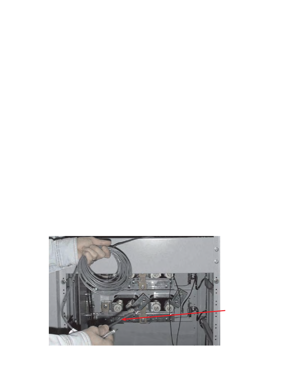
5.4.3 Temperature Probe for Monitoring Battery Temperature
1. Connect CXC temperature probes from CXC to battery termination post negative, if applicable. Pick a good
location at mid-height on one or more battery string that will provide a good average temperature reading;
i.e., away from heating or cooling sources.
Figure 21 — Temperature probe
Temp.
probe