Operator interface panel – Bell & Gossett S14367B Technologic Constant Speed Pump Controller User Manual
Page 9
Technologic
®
Constant Speed Pump Controller Installation, Operation and Maintenance Manual
9
Operator Interface Panel
2.2
LEDs
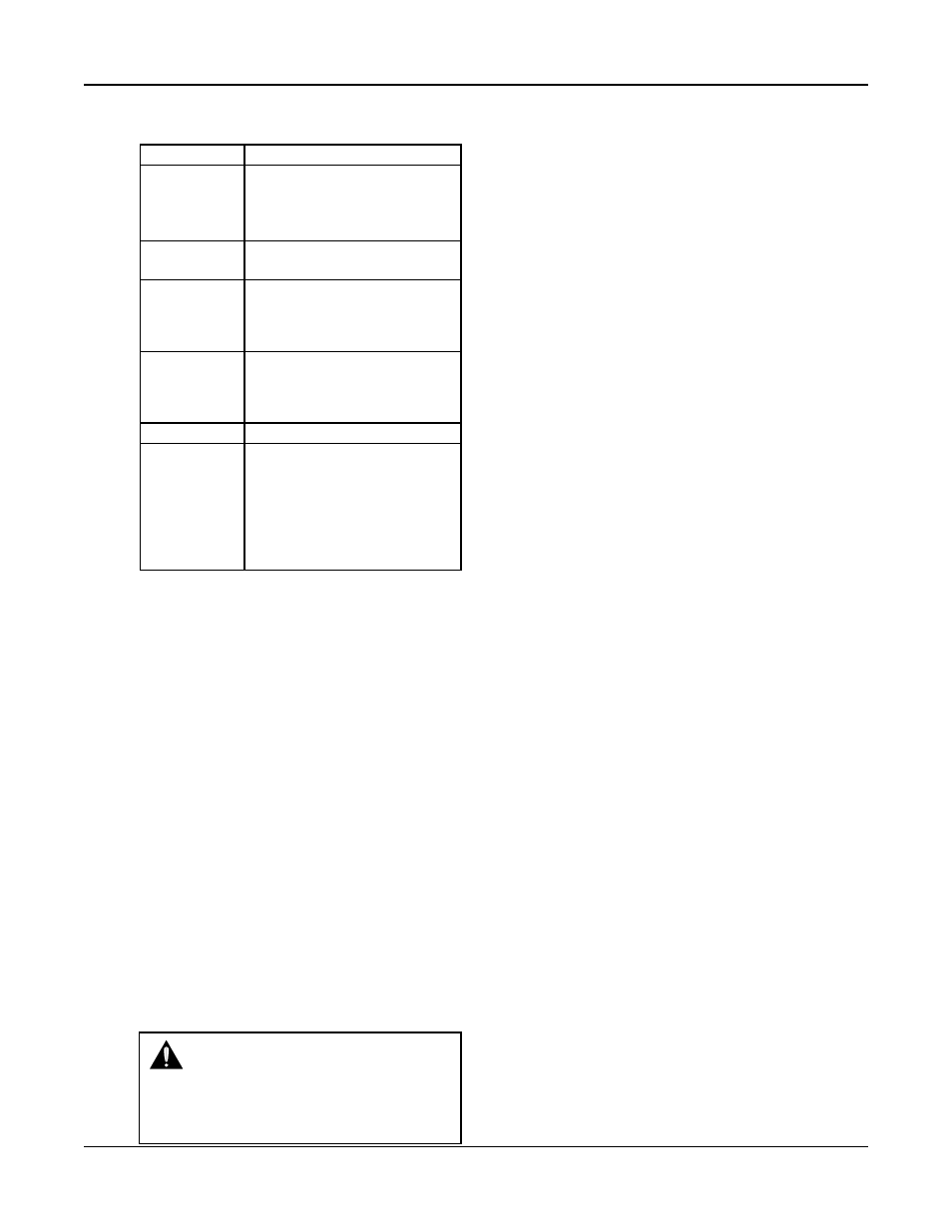
Table 2 gives the meaning of the LED states.
LED
Description
START/STOP
On = Start
Off = Stop
Blink Slow = Ready (waiting for
remote method)
AUTO/
On = Auto
MANUAL
Off = Manual
PUMP 1-6
On = Pump On
Off = Pump Disabled
Blink Slow = Pump Ready
Blink Fast = Pump Failed
RESET/
Off = OK
SILENCE
Blink Slow = Reset Required
Blink Fast = A/V Alarm output
is active
LED
Description
HELP
Off = OK
Blink Slow = Event (press HELP
from the status
screens to view)
Blink Fast = Alarm (press HELP
from the status
screens to view)
Table 2: LED Functionality
2.3
I/O
2.3.1
Analog Inputs
The Technologic
®
Constant Speed Pump Controller
is equipped with 4 analog input channels. The analog
inputs must provide a 4-20mA signal. Typically, ana-
log inputs will be powered by the 24V power supply
within the panel. For analog inputs which source
their own power, see the following section. See sec-
tion 4.1 for more information on sensor setup.
Shielded 22 AWG cable should be installed for all
analog input wiring. The shield must be terminated
in the Technologic
®
Constant Speed Pump Controller.
Do not connect the shield at the other end of the
cable! Insulate the shield so that no electrical connec-
tion is made at the other end of the cable. A twisted
pair of #22 AWG conductors can be used in place of
shielded cable. The cable length must be limited to
5,000 feet for #22 AWG wire.
2.3.2
Powered Analog Inputs
The following steps describe the general procedure
for wiring an analog input when the sensor’s power
source is not the Technologic
®
Constant Speed Pump
Controller.
WARNING:
Prevent electrical shocks.
Disconnect the power supply before begin-
ning installation. FAILURE TO FOLLOW
THESE INSTRUCTIONS COULD RESULT IN
SERIOUS PERSONAL INJURY, DEATH AND/
OR PROPERTY DAMAGE.
1) Turn off all power to the Technologic
®
Constant
Speed Pump Controller.
2) Refer to the appropriate controller wiring diagram
that was shipped with unit. Locate the analog
input sensors on the wiring diagram that will be
rewired. They are labeled AI1 – AI4.
3) Remove the 24 VDC positive (+) wire from TB 40
for the respective analog input sensor connection.
This wire needs to be removed completely or ter-
minated if used as a jumper. This will prevent any
accidental contact with a negative (-) voltage
source (i.e. control panel) and avoid becoming a
short circuit. Care should be taken to ensure that
24 VDC positive (+) voltage is still provided to
any remaining sensors that will be powered by the
Technologic
®
Constant Speed Pump Controller.
4) Remove the 24 VDC negative (-) wire from TB 41
for the respective analog input sensor connection.
This wire needs to be removed completely or ter-
minated if used as a jumper. This will prevent any
accidental contact with a positive (+) voltage
source and avoid becoming a short circuit. Care
should be taken to ensure that 24 VDC (-) nega-
tive voltage is still provided to any remaining sen-
sors that will still be powered by the Technologic®
Constant Speed Pump Controller.
5) Terminate the negative (-) wire of the sensor to TB
41 of the respective analog input sensor connec-
tion. Terminate the positive (+) wire of the sensor
to the terminal block which is connected to the
positive (+) terminal shown on the Analog input
card.
Note: Be certain that the power supplied to other
terminal blocks has not been interrupted! The wires
that were removed in the preceding steps may have
been used as jumpers.
2.3.3
RTD Inputs
The Technologic
®
Constant Speed Pump Controller
is equipped with (2) PT100 RTD input channels. (2)
RTDs will be shipped with standard units. The sys-
tem RTD will be factory mounted, on the suction
header, unless the control panel is sold separate from
the pump package. The suction RTD will be shipped
loose inside the control panel and will need to be
field mounted upstream of the suction header.
2.3.4
Digital Inputs
The Technologic
®
Constant Speed Pump Controller
is equipped with (16) 24VDC digital input channels.
This signal voltage must be obtained from the 24VDC
power supply mounted to the subpanel. It is not rec-
ommended that other power sources be used without
factory approval. All digital inputs are automatically
assigned based on Table 3. See the typical wiring dia-
gram in Appendix H.