Operation – Bell & Gossett S14367B Technologic Constant Speed Pump Controller User Manual
Page 11
Technologic
®
Constant Speed Pump Controller Installation, Operation and Maintenance Manual
11
Operation
The CLEAR key is also used to exit some screens
including: Log screens, Test screens, Info screens, and
the Alarm screen.
3.3
Pump Operation
The pumps can be controlled manually or automati-
cally. See the following sections for instructions on
both types of operation.
3.3.1
Manual Pump Operation
To manually control the pumps with the controller,
the operation mode must be set to Manual by press-
ing the AUTO/MANUAL key. Note that this key is
not allowed unless the system is stopped. The Auto/
Manual LED will be off to indicate manual opera-
tion. The system must also be started by pressing the
START/STOP key. The Start/Stop LED will be on to
indicate the system is started.
Pumps are automatically disabled when operation
mode is changed to manual. Press the corresponding
PUMP ENABLE keys to start or stop pumps. The
corresponding LED will turn solid green to indicate a
pump is on.
3.3.2
Automatic Pump Operation
To automatically control the pumps with the control-
ler, the operation mode must be set to Auto by press-
ing the AUTO/MANUAL key. Note that this key is
not allowed unless the system is stopped. The Auto/
Manual LED will be on to indicate automatic opera-
tion. The system must also be started by pressing the
START/STOP key. The Start/Stop LED will be on to
indicate the system is started.
During automatic pump operation, the pumps will
turn on or off based on the primary staging method.
If more pumps are required to meet the system
demand, they will stage on as required. When the
system demand is met, and the minimum pump run
timer is met, the pumps will destage until only one
pump is running. When there is no demand in the
system, the no flow shutdown alarm or event will
occur, shutting down the last running pump. During
this sequence, alarms may occur that shut down a
specific pump or all of the pumps. Various automatic
pump alternation methods may be used to alternate
the pump sequence at any time.
View the status screens, shown in section 3.4, to get
system information including on/off or auto/manual
status, pump status, sensor values, or staging status.
3.4
Status Screens
The status screens are the main level in screen naviga-
tion and show most of the relevant system informa-
tion. The status screens can be scrolled by pressing
PREV or NEXT.
The Setup Menu(3), Log Menu(5), Info screens(8),
Manual Alternation screen(9), and Alarm
screen(HELP) are only accessible from the status
screens.
All of the status screens will display “Alm”, “Evt”, or
“NFSD” in the lower right corner if an alarm or
event or NFSD condition exists. If this message is
flashing, press the HELP key for more details.
3.4.1
Tech Status
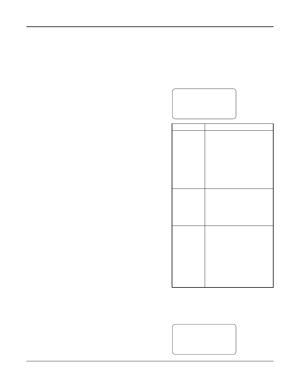
The Tech Status screen, shown below, is the first of
the status screens. This screen is displayed on power
up. See Table 4 below for a description of the Tech
Status variables.
←
TECH STATUS →
HH:MMam MM/DD/YY
Stop :(Method)
Manual Alm
Variable
Description
Start/Stop/
Stop: System is stopped. Pumps
Ready
will not start.
Start: System is started. The
pumps can be controlled manually
or automatically.
Ready: System is waiting for
remote start/stop method,
see section 4.3.4.
Press the START/STOP button
to toggle.
Method
System Start/Stop Method, see
section 4.3.4.
Key: Keypad
Rem: Remote contact
Sch: Scheduled start/stop
Ser: Serial Communications
Auto/Manual
Manual: System is in manual
operation mode. The user can
manually start and stop the pumps
by pressing the corresponding
Pump On/Off key.
Auto: The system is in automatic
operation mode. The pumps will
be controlled automatically based
on the user setup info.
Press the AUTO/MANUAL key
to toggle.
Table 4: Tech Status Variables
3.4.2
Pump Status
Pressing NEXT, the controller will display the Pump
Status screen shown below. See Table 5 for a descrip-
tion of the Pump Status variables.
←
PUMP STATUS →
1:On 2:On 3:Off
4:Rdy 5:Fail 6:Rdy
Alm