Setup menu – Bell & Gossett S14367B Technologic Constant Speed Pump Controller User Manual
Page 17
Technologic
®
Constant Speed Pump Controller Installation, Operation and Maintenance Manual
17
Setup Menu
The staging method chosen will be displayed in the
upper left corner. Press PREV or NEXT to scroll
through each staging occurrence. The staging num-
bers will increment to indicate which occurrence is
being shown. Set the value and the proof time for
each staging occurrence.
4.3.1.2 Secondary Staging
Path: Status Screens / Setup (3) / System (3) / Staging
(1) / Secondary Staging (2)
Sec Stg Mthd: Method
Stg :###(U) PT: ##s
Dstg:###(U) PT: ##s
Dynamic Stg:$ OK? $
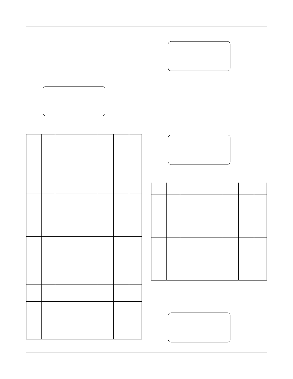
See Table 17 for a description of the Secondary
Staging variables
Variable Units Description
Default Range Field
Value
Value
Sec Stg N/A Secondary staging
Pressure Power,
Methd
method. This will be
Amps,
used if the sensor for
Press,
the primary method
D Temp,
fails. Power, Amps
Flow,
and flow staging
Temp
require nameplate
data to be set up.
See section 4.2.2.
Stg
(U) The value at which
System 0-999
pumps will stage on.
Pressure
The units depend on the – 10
staging type. This is the
stage 1-2 value and will
be used for each staging
occurrence unless Dy-
namic Stg is set to “Y”.
Dstg
(U) The value at which
System 0-999
pumps will stage off.
Pressure
The units depend on the – 3
staging type. This is the
destage 2-1 value and
will be used for each
destaging occurrence
unless Dynamic Stg is
set to “Y”.
PT
Sec- The proof timer that
5
5-99
onds will elapse before
staging pumps on/off.
Dynamic N/A Select “Y” for Dynamic “N”
Y/N
Stg
Stg to choose different
staging and destaging
values for each staging
occurrence. A separate
screen will be displayed
to allow for these inputs.
Table 17: Secondary Staging Variables
If “Y” was selected for Dynamic Stg, the screen
shown below will be displayed.
←
Method Value Time →
Stg1-2: ###(U) ##s
Dst2-1: ###(U) ##s
OK? $ (Y/N)
The staging method chosen will be displayed in the
upper left corner. Press PREV or NEXT to scroll
through each staging occurrence. The staging num-
bers will increment to indicate which occurrence is
being shown. Set the value and the proof time for
each staging and destaging occurrence.
4.3.1.3 Force Destage/Minimum Pump Run Time
Path: Status Screens / Setup (3) / System (3) / Staging
(1) / Force Dstg / Min Run (3)
Force Dstg/Min Run
Force Dstg Tmr=##Min
Min Run Timer =##Min
OK? $ (Y/N)
See Table 18 for a description of the Force Destage/
Minimum Pump Run Time variables.
Variable Units Description
Default Range Field
Value
Value
Force Min- Maximum time a lag
60
0-99
Dstg
utes pump will run prior
Tmr
to destaging auto-
matically, a value of 0
disables forced
destaging. See section
3.4.5 for display of
timer status.
Min Min- Minimum time a lag
5
0-99
Run
utes pump must run prior
Timer
to destaging, a value
of 0 effectively dis-
ables the minimum
run timer. See section
3.4.5 for display of
timer status.
Table 18: Force Destage/Minimum Pump Run Time Variables
4.3.2
Alternation
Path: Status Screens / Setup (3) / System (3) /
Alternation (2)
Alt Method: $$$$$
Basis:$$$$$ Dur:##s
Time:##:## Day: ##
Period:###Hrs OK? $