Operator interface panel – Bell & Gossett S14367B Technologic Constant Speed Pump Controller User Manual
Page 10
Technologic
®
Constant Speed Pump Controller Installation, Operation and Maintenance Manual
10
Operator Interface Panel
Functionality
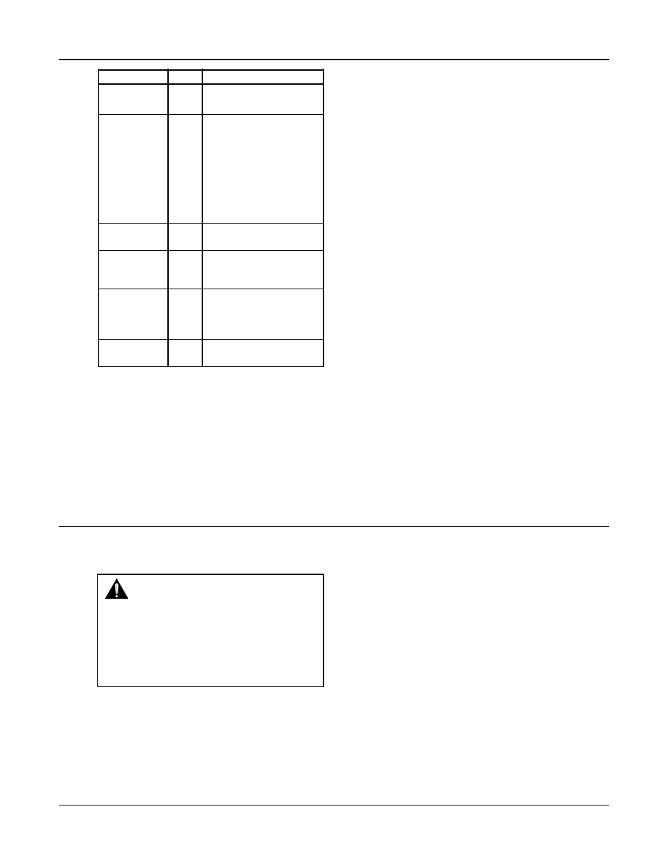
DI # Description
1M-6M
1-6
Motor starter feedbacks
Feedback
(generate overload alarm)
Start/Stop Sw
7
Remote contact can be
used to start/stop the
system. The start/stop
method must be set to
Remote. See section 4.3.4.
“Rem” will be displayed in
the Tech Status screen
shown in section 3.4.1
when this method is active.
Flow Switch
8
Used for no flow shut-
down, see section 4.5.6.
Pressure Sw
9
Used to detect low suction
pressure alarm or event,
see section 4.5.4.
Low Level
10
Low level relay to sense a
low level condition in a
tank. All pumps will stop
when active.
DP 1-6
11-16 Differential pressure
switches
Table 3: Digital Inputs Functionalities
# 22 AWG cable should be installed for all field wir-
ing to digital inputs.
2.3.5
Relay and Power Monitor Rack
The relay and power monitor rack consists of an
EX270 CAN bus controller, a DO722 digital output
module and an AI984 power measurement module.
2.3.5.1 Digital Output Module
The digital output module consists of 8 normally
open single pole single throw relays rated at 2.5A at
either 240VAC or 24VDC. One relay will be used to
energize the coil of each motor starter. These will be
factory wired. Customer connections are made direct-
ly to the terminals mounted on the digital output
module. If a relay is defective, the digital output
module must be replaced. Refer to section 4.3.8 for
relay output setup.
2.3.5.2 Power Measurement Module
The power measurement module calculates total
power by measuring the incoming voltage and the
total current from the current transformer.
2.3.5.3 Current Transformer
The current transformer (ct) comes in three different
sizes measuring up to 40A, 150A, or 400A. It plugs
directly into the AI984 module on the relay and
power monitor rack. The ct measures the total amp
draw of all motors in the system. The four digit hex
numbers displayed on the label on the current trans-
former are calibration values, unique to each ct, that
have been input into the controller prior to shipment.
See section 5.5 to view the values used.
Section 3 — Operation
3.1
Power-Up
Turn the disconnect switch “ON” to power up the controller.
WARNING:
Electrical shock hazard.
Inspect all electrical connections prior to
powering the unit. Wiring connections must be
made by a qualified electrician in accordance with
all applicable codes, ordinances and good practic-
es. FAILURE TO FOLLOW THESE INSTRUC-
TIONS COULD RESULT IN SERIOUS
PERSONAL INJURY, DEATH AND/OR
PROPERTY DAMAGE.
In order to recover from a power loss, the controller
will start up in the operating mode that it was in
prior to the last shutdown. On power up, the con-
troller will display the Tech Status screen shown in
section 3.4.1.
3.2
Basics of Screen Navigation and User
Setup
Numeric inputs (represented by the # symbol) must
be input from the numeric keypad. Text fields (repre-
sented by the $ symbol) must be modified by using
the UP and DOWN arrow keys. For numeric or text
fields, ENTER must be pressed to confirm values.
The arrow keys are also be used to navigate to neigh-
boring screens. Flashing arrows shown on the display
indicate when the corresponding arrow keys are
active.
An OK prompt is used in most user setup screens.
Press NO (the number 4 key) followed by ENTER at
the OK prompt to edit the parameters shown, or
press YES (the number 1 key) followed by ENTER to
accept the values and exit the screen.
The YES/1 and NO/4 keys are also used for text
inputs for some parameters. They will appear as “Y”
or “N” when a text input is required.