Setup menu – Bell & Gossett S14367B Technologic Constant Speed Pump Controller User Manual
Page 27
Technologic
®
Constant Speed Pump Controller Installation, Operation and Maintenance Manual
27
Setup Menu
4.7
Log Menu
Path: Status Screens / Log (5)
Log Menu: # 0=Exit ↑
1=Alarm Log
2=Pump Log Menu
3=Data Log
↓
Log Menu: # 0=Exit ↑
4=Data Log Rate
5=Operation Menu
6=Totals
↓
Log Menu: # 0=Exit ↑
7=Reset Totals
8=Log Book
↓
Press UP/DOWN to view the entire menu.
4.7.1
Alarm Log
Path: Status Screens / Log (5) / Alarm Log (1)
MMDD HHMM (alarm)
MMDD HHMM (alarm)
MMDD HHMM (alarm)
MMDD HHMM (alarm)
Every alarm that occurs will be logged with a date
and time stamp. The forty most recent alarms will be
stored. The date is displayed in MMDD format and
the time in 24 hour HHMM format. The most recent
alarm is shown first. Press UP and DOWN to view
more log events. Press CLEAR to exit.
4.7.2
Pump Log Menu
Path: Status Screens / Log (5) / Pump Log Menu (2)
Pump Log:# 0=Exit
1=Pump State
2=Pump Runtime
3=Reset Pmp Runtime
Press the numeric key corresponding to the desired
sub-menu, and press ENTER.
4.7.2.1 Pump State Log
Path: Status Screens / Log (5) / Pump Log Menu (2) /
Pump State (1)
Pump State
Pump # 1
MM/DD
(state)
HH/MM
Scr# 1
Each time a pump’s state changes, the date and time
are recorded along with the new pump state. The
sixty most recent pump state changes will be stored.
Possible states are ON, RDY, OFF, and FAIL. The
date is displayed in MMDD format and the time in
24 hour HHMM format. Press UP/DOWN to view
more log events. Press CLEAR to exit.
4.7.2.2 Pump Runtime Log
Path: Status Screens / Log (5) / Pump Log Menu (2) /
Pump Runtime (2)
Pump Run Time Log
P1:### P2:### P3:###
P4:### P5:### P6:###
OK? $ (Y/N)
The pump runtimes may be used to automatically
alternate the pump staging sequence so that the pump
with the lowest runtime will be the lead pump. See
section 4.3.2 for more information on alternation.
The runtime is continuously recorded for each pump
and is displayed in hours. To reset the pump runtimes
see section 4.7.2.3.
4.7.2.3 Reset Pump Runtime
Path: Status Screens / Log (5) / Pump Log Menu (2) /
Reset Pmp Runtime (3)
Reset Pump Runtime?
P1:$ P2:$ P3:$
P4:$ P5:$ P6:$
OK? $ (Y/N)
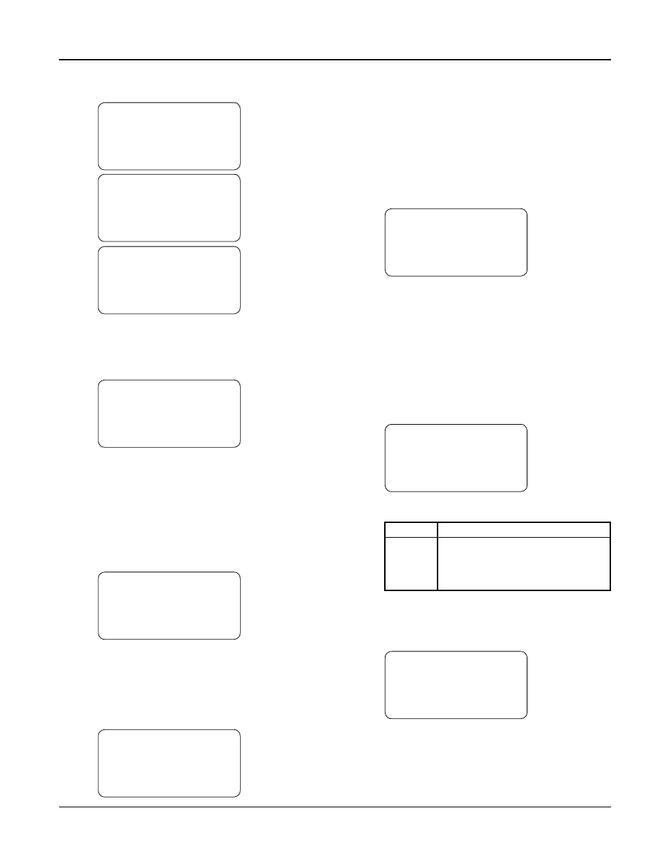
See Table 39 for a description of the variables.
Variable Description
P1-P6
Enter a “Y” next to each pump for
which the runtime will be reset. To
view the pump runtimes, see section
4.7.2.2.
Table 39: Reset Pump Runtime
4.7.3
Data Log
Path: Status Screens / Log (5) / Data Log (3)
AI/RTD#
(Type)
Max=#####
MM/DD
Min=#####
HH:MM
Avg=#####
Scr# 1
The Data Log screen will show the minimum, maxi-
mum and average values for each analog input and
RTD input channel. The sixty most recent data log
intervals will be stored. The analog input or RTD
channel along with the type of sensor set up for that
channel will be displayed on the top line. Press NEXT