Setup menu – Bell & Gossett S14367B Technologic Constant Speed Pump Controller User Manual
Page 28
Technologic
®
Constant Speed Pump Controller Installation, Operation and Maintenance Manual
28
Setup Menu
and PREV to scroll through the analog input and
RTD channels. Press UP and DOWN to change the
Scr # showing the next log event for that sensor. The
date is displayed in MMDD format and the time in
24 hour HHMM format. See section 4.7.4 to change
the data log rate. Press CLEAR to exit.
4.7.4
Data Log Rate
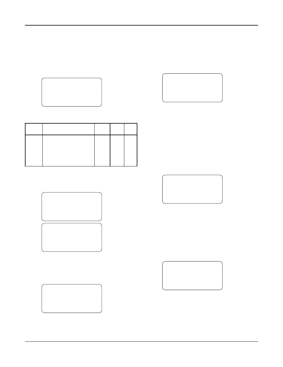
Path: Status Screens / Log (5) / Data Log Rate (4)
Data Log Rate:$$$$$$
OK? $ (Y/N)
See Table 40 for a description of the Data Log Rate
variables.
Variable Description
Default Range Field
Value
Value
Data
One data point for the data
None None,
Log
log is taken at the end of
Minute,
Rate
each interval defined by the
Hour,
Data Log Rate
Day
Week,
Month
Table 40: Data Log Rate Variable
4.7.5
Operation Log Menu
Path: Status Screens / Log (5) / Operation Menu (5)
Op Log Menu:# 0=Exit
1=Op Mode Changes ↑
2=Power Cycles
↓
3=Events Log
Op Log Menu:# 0=Exit
4=Purge Log
↑
5=Exercise Log
↓
6=Operating Hours
Press UP/DOWN to view the entire menu.
4.7.5.1 Operation Mode Changes Log
Path: Status Screens / Log (5) / Operation Menu (5) /
Op Mode Changes (1)
Operation Mode
MM/DD
Start/Manual HH/MM
Scr# 1
Every time the START/STOP key or the AUTO/
MANUAL key is pressed, the event will be logged by
showing the state of both variables immediately after
the change. The sixty most recent operation mode
changes will be stored. The date is displayed in
MMDD format and the time in 24 hour HHMM for-
mat. The most recent event will be shown first. Press
UP/DOWN to change the Scr # showing the next log
event. Press CLEAR to exit.
4.7.5.2 Power Cycles Log
Path: Status Screens / Log (5) / Operation Menu (5) /
Power Cycles (2)
MMDD HHMM Power Up
MMDD HHMM Power Down
MMDD HHMM Power Up
MMDD HHMM Power Down
Each time the controller is powered up or down, the
event will be logged. “Power Up” will be shown if
powered up, and “Power Down” will be shown if
powered down. The sixty most recent power cycles
will be stored. The date is displayed in MMDD for-
mat and the time in 24 hour HHMM format. The
most recent event will be shown first. Press UP/
DOWN to view the next log event. Press CLEAR to
exit.
4.7.5.3 Events Log
Path: Status Screens / Log (5) / Operation Menu (5) /
Events Log (3)
MMDD HHMM Event
MMDD HHMM Event
MMDD HHMM Event
MMDD HHMM Event
Each time an event occurs, it will be logged. The
forty most recent events will be stored. The date is
displayed in MMDD format and the time in 24 hour
HHMM format. The most recent event is shown
first. Press UP/DOWN to view more log events. Press
CLEAR to exit.
4.7.5.4 Purge Log
Path: Status Screens / Log (5) / Operation Menu (5) /
Purge Log (4)
Purge MM/DD HH:MM
Log
MM/DD HH:MM
MM/DD HH:MM
MM/DD HH:MM
Each time purging occurs, it will be logged. See sec-
tion 4.3.11 to set up purging. This option will only
be available for Tech 350 applications. The forty
most recent purges will be stored. The date is dis-
played in MMDD format and the time in 24 hour
HHMM format. The most recent event is shown
first. Press UP/DOWN to view more log events. Press
CLEAR to exit.