Operation – Bell & Gossett S14367B Technologic Constant Speed Pump Controller User Manual
Page 12
Technologic
®
Constant Speed Pump Controller Installation, Operation and Maintenance Manual
12
Operation
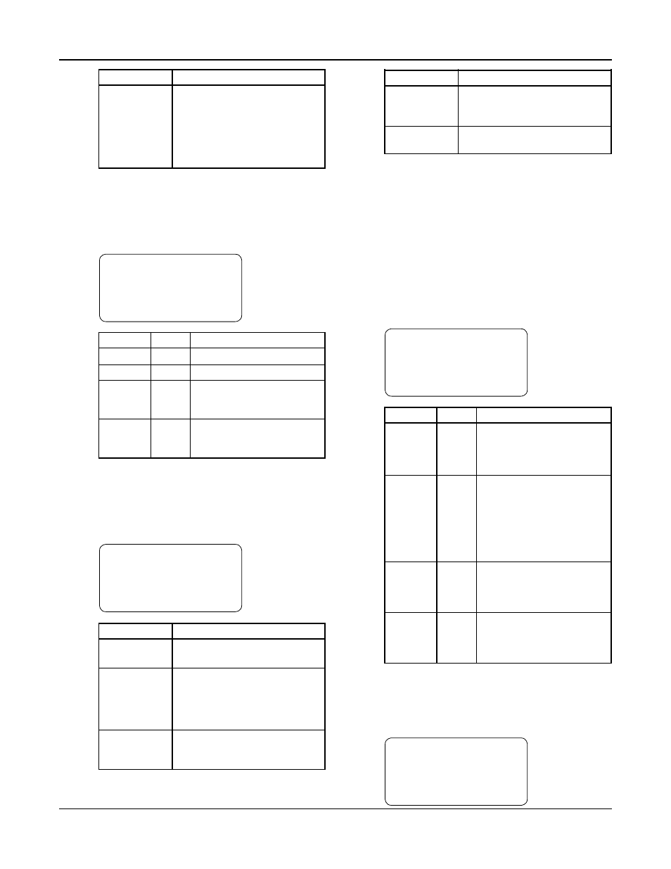
Variable
Description
P1-P6
On: pump is running
Off: pump is disabled from the
keypad
Rdy: pump is enabled but not
running
Fail: pump is failed
Table 5: Pump Status Variables
3.4.3
Sensor Status
Pressing NEXT, the controller will display the Sensor
Status screen shown below. See Table 6 for a descrip-
tion of the Sensor Status variables.
←
Suc Press= ### →
Sys Press= ###
Suc Temp=###.#
Sys Temp=###.# Alm
Variable
Units Description
Suc Press
PSI
Suction Pressure
Sys Press
PSI
System (discharge) Pressure
Suc Temp
°F
Suction Temperature
(mounted upstream of the
suction header)
Sys Temp
°F
System Temperature
(mounted on the suction
header)
Table 6: Sensor Status Variables
3.4.4
Staging
Pressing NEXT, the controller will display the Staging
screen shown below. See Table 7 for a description of
the Staging variables.
←
STAGING: (Type) →
Stg Seq:1-2-3-4-5-6
Dstg: #### Stg: ####
Actual: ###.# Alm
Variable
Description
Type
Type will display the active staging
method.
Stg Seq
Pump staging sequence from left
to right. A 0 indicates that a pump
is failed or disabled. See section
4.3.2 for information on alternat-
ing the staging sequence.
Stg
Next staging value (N/A indicates
end of staging sequence or no
staging values set up)
Variable
Description
Dstg
Next destaging value (N/A indi-
cates end of destaging sequence
or no destaging values set up)
Actual
Current value of the staging
variable
Table 7: Staging Variables
Note: “Stg” and “Dstg” will be displayed in units of
the active staging method shown in the “Type” field.
To change the staging type or values, see section
4.3.1.
3.4.5
Timers
Pressing NEXT, the controller will display the Timers
screen shown below. The numeric values on the left
are elapsed times, and the numeric values on the right
are the limits that they must reach prior to perform-
ing their respective action. See Table 8 for a descrip-
tion of the Staging variables.
←
Pump MnRn:##/##m →
NFSD MnRn:###/###m
Stg PT:##/##
Dstg PT:##/## Alm
Variable
Units Description
Pump Min Minutes Pump minimum run time,
Run
see section 4.3.1.3. When the
timer reaches its limit pumps
will be allowed to destage.
NFSD
Minutes No flow shutdown minimum
MnRn
run time, see section 4.5.6.
When the timer reaches its
limit, a no flow shutdown
will be allowed to occur. Note
that the timer immediately
resets to zero after expiring.
Stg PT
Seconds Staging proof timer, see
section 4.3.1.1. When the
timer reaches its limit,
another pump will stage on.
Dstg PT
Seconds Destaging proof timer, see
section 4.3.1.1. When the
timer reaches its limit, a
pump will stage off.
Table 8: Timers Variables
3.4.6
Power
Pressing NEXT, the controller will display the Power
screen shown below.
←
POWER
→
HP= ###.# PF= #.##
Volts= ###.#
Amps = ###.# Alm