Maintenance – Bell & Gossett S14367B Technologic Constant Speed Pump Controller User Manual
Page 31
Technologic
®
Constant Speed Pump Controller Installation, Operation and Maintenance Manual
31
Maintenance
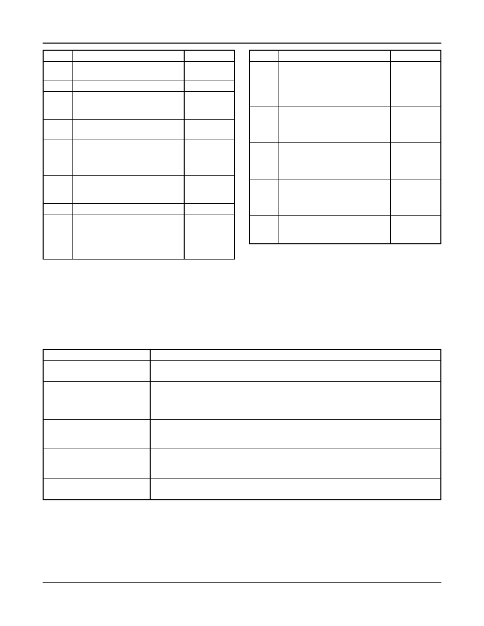
Variable Description
Range
Job #
QM or QB
service calls
0000-9999
Ver
Software version number
1.0 – 9.99
Volts
Incoming Voltage, used as the
208/230/
nominal value for the voltage
460/575
tolerance alarm
App
Application type (70E = open
70E/350
system, 350 = closed system)
Comms Serial communication protocol
BACnet,
Modbus,
JC N2,
Lonworks
3Φ
“Y” should be selected for three
Y/N
phase voltage and “N” should be
selected for single phase.
Suc Pr Suction Pressure
0-999
Sys Pr System Pressure, used to set default 0-999
alarm values for high suction
pressure, low system pressure, high
system pressure, and the restart
PSI for no flow shutdown
Variable Description
Range
#
Number of pumps that were
1-6
Pumps entered by the factory (Total
number, number of jockey pumps,
number of standby pumps), see
section 4.2.1.
CT
Size of the current transformer in 40, 150, 400
amps, this must be correct for
proper amp and power
measurement.
G
Gain for CT calibration (printed
Hex values
on the label on the CT), this must 0-F
be correct for proper amp and
power measurement.
O
Offset for CT calibration (printed Hex values
on the label on the CT), this must 0-F
be correct for proper amp and
power measurement.
HP1-6 Horsepower for each pump that
0-999.9
was entered by the factory, see
section 4.2.2.
Table 43: Info Screens Variables
Note: There are redundant setup screens for horse-
power and number of pumps. The values entered
here are used to set default values only. The actual
parameters used for operation are shown in section
4.2 and may be different than the values shown here.
5.6
Troubleshooting
Problem
Solution
Service Mode LED
Set the node switches on the controller to 0 and 0 and cycle power. Set the node switches
(blank screen)
back to 1 and 1 and cycle power again.
Pump won’t start
Check that the Start/Stop LED is on. Check that the pump status LEDs are blinking to
indicate that they are ready. Press the HELP key from the status screens to check the alarm
screen for any conditions that may prevent the pumps from running. If the RESET/
SILENCE LED is flashing, a manual reset of the system is required.
Pumps won’t stage on/off
Check the Staging screen to see what the staging method is and what the next staging values
are. See section 3.4.4. Check the timers screen to be sure that the pump minimum run timer
is expired prior to destaging. See section 3.4.5.
No Flow Shutdown will
Check the Timers screen to be sure that the NFSD minimum run time has expired. Only
not occur
one pump must be running and the system pressure must be greater than the NFSD restart
pressure in order for NFSD to occur. See section 4.5.6.
Inaccurate amps, voltage
Check that the calibration values printed on the label on the current transformer correspond
or power readings
to the values shown in the Info screens. See section 5.5.
Job #, this will be helpful for