1 key functionality – Bell & Gossett S14367B Technologic Constant Speed Pump Controller User Manual
Page 8
Technologic
®
Constant Speed Pump Controller Installation, Operation and Maintenance Manual
8
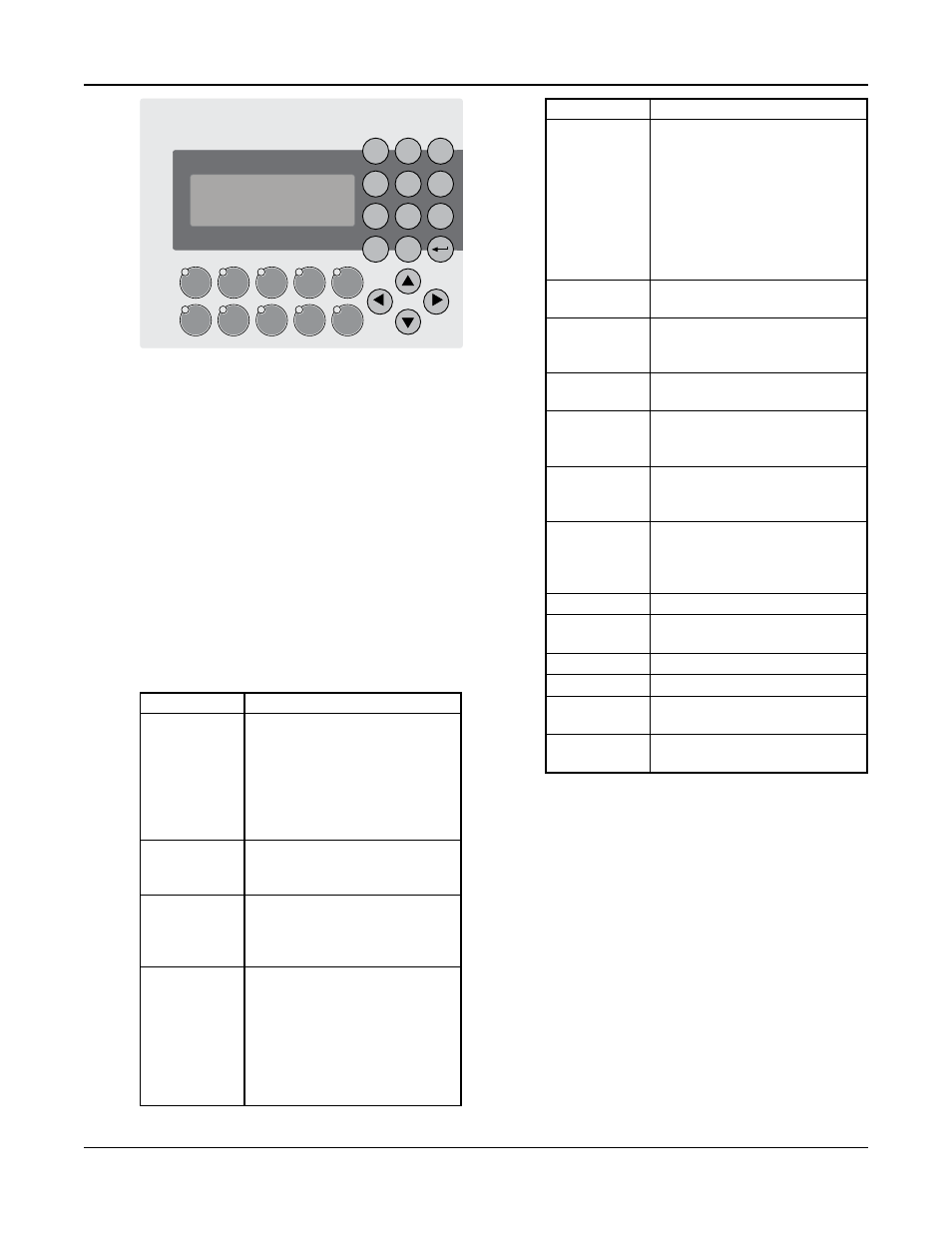
The OIP consists of a 4 x 20 character LCD screen
and a 26 button keypad with LEDs which display sys-
tem status. It also is equipped with onboard I/O
including (16) 24VDC digital inputs, (4) 4-20mA
analog inputs, (2) PT100 RTD inputs, and an RS232/
RS485 serial port for communications all mounted
on the back of the OIP. The OIP communicates
through a CAN bus to the relay and power monitor
rack.
2.1
Key Functionality
The names of the keys on the Operator Interface
Panel (OIP) are shown as CAPITAL LETTERS in this
manual. Table 1 shows the functionality of the keys
on the OIP.
Note: The contrast can be adjusted from any screen
by pressing the UP and DOWN arrows while holding
the ENTER key.
Key Name
Functionality
START/STOP
Starts or stops the system. When
the Start/Stop method is not
“Keypad”, pressing the START/
STOP key will toggle between
“Ready” and “Stop”. “Ready”
indicates the system is waiting
for a remote signal to start.
AUTO/
Toggles the operation mode. The
MANUAL
system must be stopped to
change the operation mode.
PUMP 1-6
Enables or disables the
ENABLE
corresponding pump. Pumps
cannot be disabled while they
are failed.
RESET/
This key is used to reset pumps
SILENCE
and alarms. When the A/V Alarm
relay output (section 4.3.8) is
set, initial pressing of this key
opens the relay to silence the
horn or turn off the pilot light.
Pressing a second time resets the
pumps and alarms.
Key Name
Functionality
HELP
Press the HELP button, from the
status screens, to view alarms or
events while the HELP LED is
flashing. While in the Alarm
screen, press the HELP button
again to view help messages for
active alarms. Press HELP any
other time to view screen
specific help messages.
YES/1
Press YES at OK prompts to
accept values and proceed
SETUP/3
Press SETUP, from the status
screens, to bring up the Setup
Menu shown in section 4
NO/4
Press NO at OK prompts to edit
the parameters
LOG/5
Press LOG, from the status
screens, to bring up the Log
Menu, shown in section 4.7
INFO/8
Press INFO, from the status
screens, to bring up the Info
screens, shown in section 5.5
ALT/9
Press ALT, from the status
screens, to manually alternate
the pump staging sequence, see
section 4.3.2
ENTER
Confirms entries
CLEAR
Clears entries or used to exit
some screens
PREV (←)
Navigates to neighboring screens
NEXT (→)
Navigates to neighboring screens
UP (↑)
Used to modify values and
navigate to neighboring screens
DOWN (↓)
Used to modify values and
navigate to neighboring screens
Table 1: Key Functionality
1
Yes
2
3
Setup
4
No
5
Log
6
7
8
Info
9
Alt
Clear
0
Enter
Technologic
®
Constant Speed Pump Controller
Next
Prev
GREEN = RUN
OFF = STOP
GREEN = AUTO
OFF = MANUAL
ON SOLID-PUMP RUNNING
OFF-PUMP DISABLED
FLASH SLOW-PUMP READY
FLASH FAST-PUMP FAILED
Start /
Stop
Pump 1
Enabled
Pump 2
Enabled
Pump 3
Enabled
Reset /
Silence
Auto /
Manual
Pump 4
Enabled
Pump 5
Enabled
Pump 6
Enabled
Help
Section 2 — Operator Interface Panel