Temperature, Range low and high control, Directions to configure temperature sensor – YSI 5200A User Manual
Page 73: Salinity
YSI 5200A
144
YSI 5200A
145
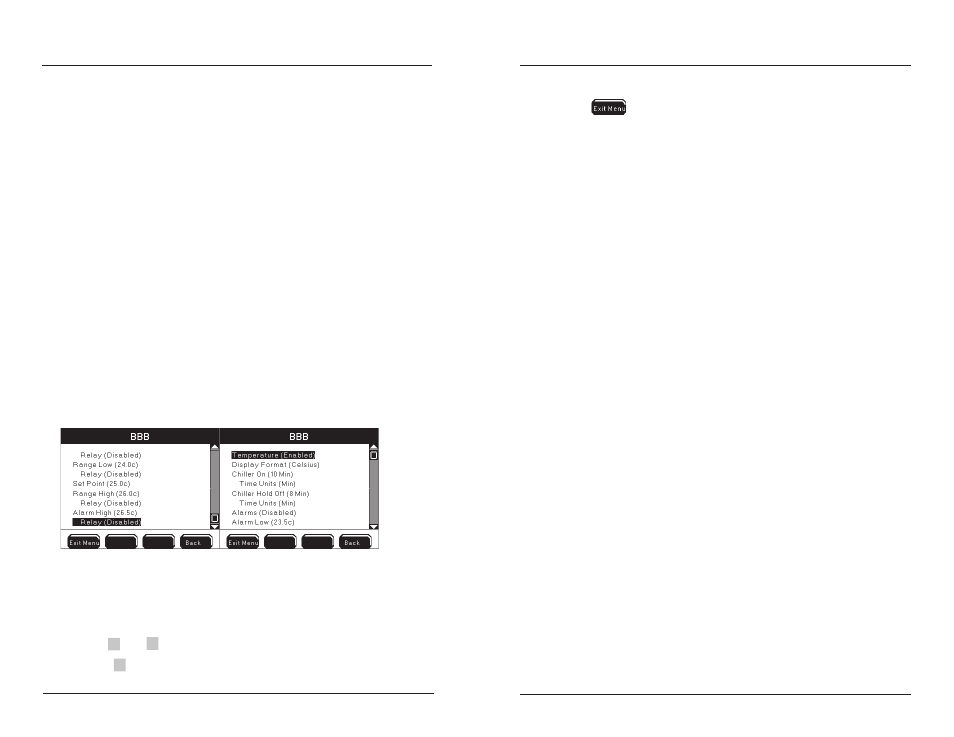
Temperature
Menus →Sensor Setup→Temperature
See Set Points, Control, and Alarms - page 128 before configuring the temperature
system. Since most heaters and chillers have their own thermostats, their thermo-
stats can be used as a backup temperature control system. Set the heater thermostat
several degrees above the desired temperature and the chiller thermostat several
degrees below the desired temperature.
Range Low and High Control
Temperature high control can operate in two different modes, normal or timed.
Temperature low control operates in normal mode only. In the normal mode, control
relay is energized until the set point value is reached. For normal control configure,
set chiller on time to 0. The chiller off time will be ignored.
In temperature high control timed mode, the control relay is energized for the chiller
on time, regardless if the sensor value has returned to the set point value. Chiller off
time is user selectable. To avoid chiller compressor damage, configure the chiller
hold off time to a value of eight (8) minutes or more. After chiller on time expires,
the control relay de-energizes for the configured chiller off time. After the chiller off
time expires and if the value is still in control range, the control relay will reenergize.
A chiller off time must be configured in the timed mode or the control relay will
never de-energize regardless of sensor value.
Directions to Configure Temperature Sensor
Connect probe assembly -
1.
page 60.
Enter Temperature Sensor Setup menu
2.
Menus →Sensor Setup→Temperature
Use
3.
▲
and
▼
to scroll and highlight submenus.
Press
4.
to select.
Configuring the 5200A
Configure submenus.
5.
Press
6.
to save configuration and return to Run Screen.
Notes:
Celsius temperature set point, control, and alarm values are configured
-
to the 10ths digit. Fahrenheit values are configured to the 100ths digit.
However, Fahrenheit display values and temperature system operation
are based on values truncated to the 10ths digit.
See 30 Second Sensor Hold Off
-
- page132.
Active sensor control timers are reset after systemwide events. Systemwide
-
events de-energize relays. Example - chiller on time is configured for eight
(8) minute on time. Energized chiller (control down) relay de-energizes
when 5200A goes into Svr Hold. The chiller on relay had been energized
for three (3) minutes before the Svr Hold occurred. Svr Hold time is
one (1) minute. After Svr Hold time expires, the sensor control system
is reset. If sensor is reporting control low condition, the chiller on time
will be for eight (8) minutes and not the remaining five (5) minutes of
the chiller on time prior to Svr Hold.
Temperature display format (°C or °F) is user selectable. Changing the
-
temperature scale automatically recomputes set points.
Temperature values are stored in the sensor data log in °C regardless of
-
display format.
Temperature values affect DO, conductivity, and pH values. It is important
-
to verify that the temperature sensor is measuring accurately.
Control down relay (chiller) energizes for original “on time” if chiller “on
-
time” is reconfigured when relay is energized.
Salinity
Menus →Sensor Setup→Salinity
When enabled, the salinity system will display a ppt value computed from the 5200A
conductivity sensor.
Notes:
When conductivity is enabled, salinity is ALWAYS calculated by the
-
conductivity sensor value regardless if salinity is enabled. This value is
used in the DO mg/L calculation.
The salinity value is displayed at the Run Screen when salinity is en-
-
abled.
Salinity cannot be enabled when conductivity is disabled.
-
The 5200A can display ppt values up to 80 ppt when calculated from the
-
conductivity sensor.
Configuring the 5200A