Step 9 connect probe/cable assembly, Lightning and surge protection, Sealants, desiccants, and securing 5200a – YSI 5200A User Manual
Page 31
YSI 5200A
60
YSI 5200A
61
Notes:
See
-
Menus → System → Communications → Ethernet beginning on page 88
for configuration information.
An SMTP server accessible by the local network must be provided by your
-
local IT support for ethernet connection.
Consult the network administrator to verify compatibility of ethernet configura-
tion.
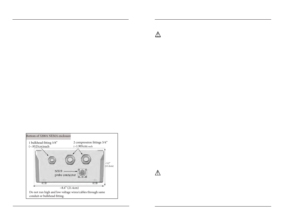
Step 9 Connect Probe/Cable Assembly
Either a YSI 5561(DO & temp) or YSI 5562 (DO, temp, conductivity, pH & ORP)
probe/cable assembly can be used with the 5200A. Both probe/cable assemblies
have an MS19 connector (Military Spec). Connect the probe/cable assembly as
described below.
Directions to Connect Probe/Cable Assembly
Perform steps 1 - 4 of 5200A installation.
1.
Line up pins and guides with the holes and indentations on the cable con-
2.
nector at the bottom of the YSI 5200A - figure 3.30.
Hold the cable firmly against the cable connector; then, turn the locking
3.
mechanism clockwise until it snaps into place. (Remove the cable from
the instrument by turning the cable connector counterclockwise until the
cable disengages from the instrument.)
Figure 3.30
Installation and Wiring
Notes:
Calibrate sensors prior to use. See
-
calibration - page 72
-
CAUTION
: Do not ground the probe body.
Lightning and Surge Protection
AC line voltage surge suppressors protect field equipment on any AC line-to-ground
from damage due to electrical transients induced in the interconnecting power lines
from lightning discharges and other high voltage surges. Surge protection devices
are strongly recommended to protect your equipment from secondary surges and
lightning on outdoor installations. Follow the recommendations provided when
choosing and incorporating surge protection devices into your operation:
Recommendations:
Surge suppression devices should be located on the AC line supplying
•
power to the 5200A and any signal lines connecting the 5200A.
The unit should include noise filtering, common mode, and normal mode
•
suppression and nanosecond reaction time.
Surge suppressors should be internally-fused to remove the load if the unit
•
is overloaded or the internal protection fails.
Signal line suppressors protect low voltage signals and relay outputs from
•
damage due to electrical transients induced in the signal lines from light-
ning discharges or nearby electrical devices.
Signal line suppressors should be installed at each end of an analog loop.
•
Relay outputs should be protected at the receiver end.
•
Signal line suppressors should consist of a three-element gas tube followed
•
by metal oxide varistors and suppressor diodes.
The protective elements should be matched such that high-energy surge
•
voltages trigger the gas surge arrester, while low energy or surge voltages
affect the MOV’s and suppressor diodes.
Lightning protection devices should be located as close to the 5200A as
•
possible and wired in accordance with the
National Electric Code in ap-
proved watertight enclosures.
CAUTION: This or any other installation procedure cannot protect against a
direct lightning strike. YSI Incorporated cannot accept liability for damage
due to lightning or secondary surges.
Sealants, Desiccants, and Securing 5200A
Environmental conditions can promote the formation of condensation in and around
Installation and Wiring