Menus – YSI 5200A User Manual
Page 35
YSI 5200A
68
YSI 5200A
69
Notes:
Control icons display when control relay(s) is active.
-
General alarm icon, buzzer, 5200A emails, and enabled alarm relay(s) [sen-
-
sor and general alarm] remain active until one of the bottom four 5200A
front panel softkeys is pressed, regardless if the alarm condition no longer
exists.
Relays, and corresponding icons, that de-energize for Svr Hold, calibra-
-
tion, and/or factory resets are restored after 30 seconds of completing Svr
hold, calibration, and/or factory resets. For exceptions, see menu specific
information in this chapter.
With alarms enabled, alarm icons appear at the systemwide location and
-
individual system location regardless if a relay is assigned to the sensor
alarm or general alarm system.
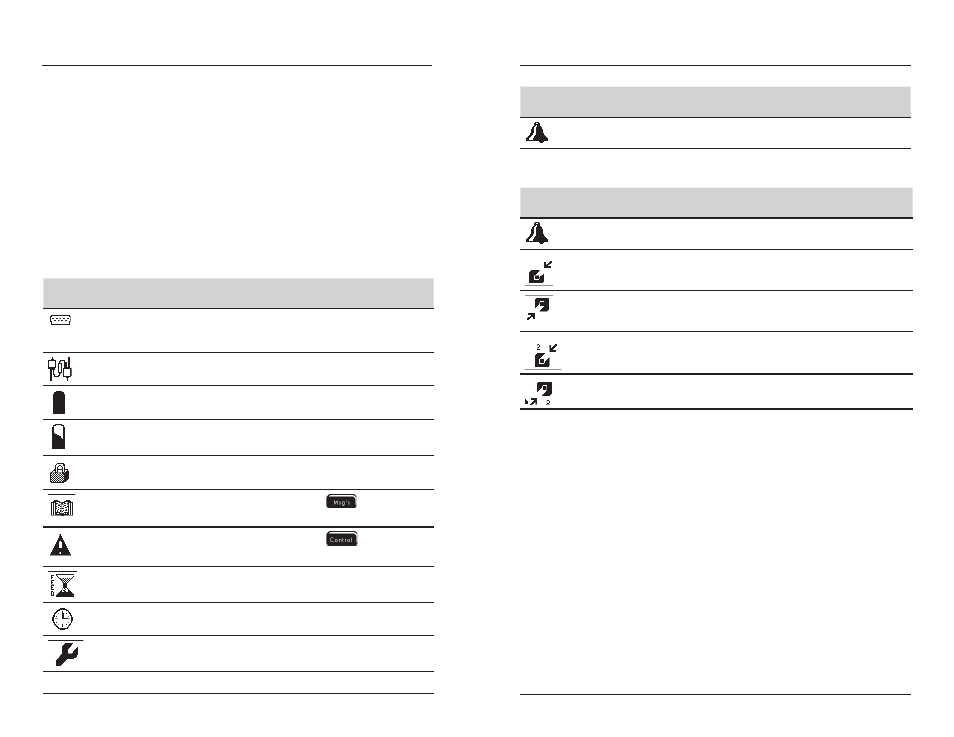
ICONS
(Systemwide)
Significance
Notes
RS232 communication
blinking icon indicates
“force serial port” is
enabled
TCP/IP communication
ethernet module installed
operating in acceptable DC power range
DC power is ≤ low battery trigger
5200A is password protected
log(s) have data
to view logs
one or more control systems is active
to view active systems
feed timer is active
one or more 10 event timer is active
clean probe timer has expired
Configuring the 5200A
ICONS
(Systemwide)
Significance
Notes
General Alarm is active
Table 4.2
ICONS
(Sensor & Aux) Significance
Notes
sensor system is in alarm
low range control relay is energized
(to raise sensor value)
control icons do not appear
for aux systems
high range control relay is energized
(to lower sensor value)
control icons do not appear
for aux systems
DO low range 2 control relay is
energized (to raise sensor value)
DO high range 2 control relay is
energized (to lower sensor value)
Table 4.3
Menus
5200A firmware is structured using menus that enable you to easily configure and
view system status, messages, and logs. The menu structure and screen formats are
very intuitive. Menus are structured in hierarchical fashion. See Appendix 3 “Menu
Maps” - beginning on page 194. For example, figure 4.3 illustrates the menu path
to configure data logging interval.
Configuring the 5200A