Ysi 5562 probe assembly, Wiring information, Pcbs 5200a bulkhead fittings – YSI 5200A User Manual
Page 19
YSI 5200A
36
YSI 5200A
37
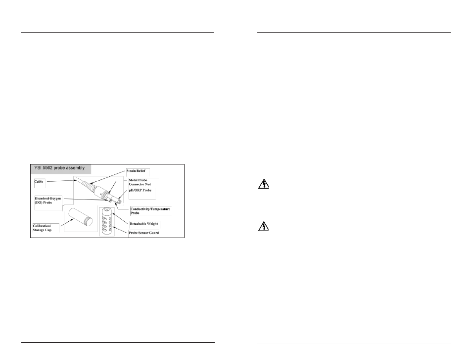
YSI 5562 Probe Assembly
Depending on the sensor configuration, the YSI 5562 probe assembly is capable of
measuring DO, temperature, conductivity, pH, and ORP. The DO sensor is shipped
uninstalled and with a dry membrane. Install the sensor onto the cable assembly
following the instructions provided with the cable. A new membrane with fresh
electrolyte must be installed on the DO sensor prior to use.
Notes:
- Replace the dry, shipping cap membrane with a 2 mil PE (blue) membrane
or 2.0 mil Teflon (gray) membrane following the instructions provided
with the membrane kit.
Do not discard the calibration/storage cup. It is used for calibrating and
-
storing the sensors when not in use.
Allow approximately 10 to 15 minutes after the 5200A is powered, or after
-
servicing the DO sensor, for the polarographic DO sensor to stabilize.
Figure 3.12 shows the external parts of the YSI 5562 probe assembly.
Figure 3.12
Wiring Information
System components must be wired correctly to ensure reliable performance and
accurate data collection. Directions are provided in this section for wiring all com-
ponents and peripheral devices.
PCBs
There are three printed circuit boards (PCBs) inside the 5200A enclosure. They
are:
Installation and Wiring
-Display board (mounted in the front panel)
-I/O board (visible when front panel is removed)
-Control board (connected to the under side of the I/O board)
Notes:
- I/O and Control boards are attached to a metal plate and are referred to
as the “lower board assembly”. See Control Board - page 40.
No 5200A components or peripheral devices are wired to the display
-
board.
Most components including power, ground, Aux input, network, relay output, and
RS232 communication components are terminated on the I/O board. The optional
serial to ethernet device is installed on the control board. The front panel must
be removed when wiring 5200A components and peripheral devices (except for
the probe assembly). See Accessing the I/O Board - page 39. It is recommended
that some system configuration and testing be done in conjunction with hardware
installation. This will ensure that the 5200A system is wired correctly. Necessary
configuration information (from Chapter 4 - “Configuration”) is referenced in the
applicable test system procedures.
WARNING: Follow all safety information and local electrical codes when
wiring 5200A system components and peripheral devices
. Proper wire gauge
should be determined based on voltages and wire/cable length. Incorrect wir-
ing can result in damage to you or to the equipment. Improper wiring can also
result in ground loops.
AVERTISSEMENT : suivez toutes les consignes de sécurité et les codes électriques
en vigueur lors du câblage des composants du système 5200A et des appareils
périphériques. Le calibre correct des câbles doit être déterminé en fonction des
tensions et de la longueur des câbles/fils. Un câblage incorrect peut entraîner
des blessures et endommager l’équipement. Un câblage incorrect peut également
entraîner des boucles de mise à la terre.
5200A Bulkhead Fittings
Three bulkhead fittings [2@ 3/4” (1.905cm) and 1@ 3/8” (.9525cm)] located at the
bottom of the 5200A enclosure provide watertight entry points for 5200A system
wiring. The probe/cable assembly connector is located below the bulkhead fittings
- figure 3.13. Rubber grommets must be “pushed out” of the compression fitting
housing and drilled for wiring installation. The drill bit diameter should be slightly
smaller than the wire diameter so that a watertight seal can be made. Rubber grom-
mets can be frozen (put in a freezer for 1 hour) and then easily drilled to the required
diameter. Some pre-drilled rubber grommets are supplied with the 5200A.
Installation and Wiring