4 the trolley – GE Industrial Solutions DC OEM Module For use with Gerapid DC Circuit Breaker User Manual
Page 9
DC OEM MODULE FOR USE WITH GERAPID CIRCUIT BREAKERS
Chapter 4 Installing the Module
2011-04-26 S47183Ee rev.01
Design and specifications are subject to change without notice
9
Grounded steel barriers on the top, sides, bottom, and front
enclose the breaker compartment. In the back, a flame-retardant,
track resistant, glass-filled polyester base minimizes the possibility
of fault communication between compartments or to the bus.
Breaker compartment has primary stabs for connecting the
breaker. Insulated shutters cover primary stabs. See Fig 33-2.
NOTE: See Appendix A for all dimensional drawings of the
breaker Compartment.
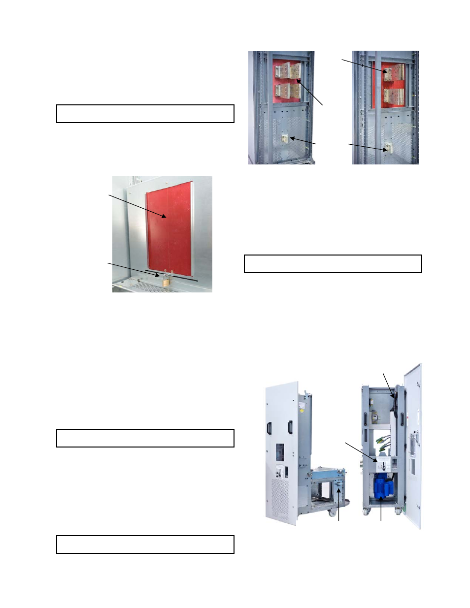
Primary disconnect shutters are provided as standard feature to
provide protection against contact with the energized stationary
primary stabs when the trolley is removed from its compartment.
The shutters are constructed from fiberglass reinforced thermoset
polyester. A padlock can lock the shutters in the closed position.
See Fig. 33-3.
Fig. 33-3 Safety padlock on the shutters
Every module is equipped with rejection Interlock that must be
properly configured by the OEM. This interlock allows
configurations for all current ratings. It is placed on both sides of
the breaker compartment. See Fig. 33-2.
Cable Compartment
The primary stabs extend into the cable compartment and are
suitable for connection with ANSI type busbars. Fig 33-4 shows
primary terminals for 4000A and 6000 A rated modules. Ground
bus connection in the cable compartment is the same on all
module types. Cable compartment is provided without side
covers. See Fig. 33-1. Painted and pre-punched side covers can
be ordered as separate accessories.
NOTE: See Appendix A for all dimensional drawings of the
primary terminals and cable compartment.
Module is also equipped with trolley-operated contacts that are
activated in CONNECTED and TEST position as well as with some
other limit switches that are used for internal interlocks.
Control Compartment
The secondary control plug located in the breaker compartment
is prewired, with a 3ft tagged wire harness brought into the
controls compartment for User’s connections. The matching
secondary disconnect plug is mounted on the trolley.
NOTE: See Appendix A for all dimensional drawings of the
Control Compartment.
Fig. 33-4 Rear views of 4000A and 6000A Modules
3-4 The Trolley
The module is designed to be used with Gerapid high-speed
circuit breaker installed on the withdrawable trolley. The trolley
can be ordered in two different versions, with manual racking or
with motor operated remote racking system.
Remote racking trolley equipped with motor drive can also be
operated manually by the crank handle.
NOTE: The crank handle is an accessory and has to be
ordered separately.
Trolley structure is compatible with all the modules and all
Gerapid circuit breakers listed in Section 3-5. The OEM must
correctly configure the rejection Interlock on the trolley and in the
module for the specific rating of breaker being installed.
All breaker controls, control power supply and auxiliary contacts
are extended to the control compartment via the secondary
disconnect and harness. Negative and positive interlocks are
operated from access console at the front of the trolley. The
access opening for the manual crank handle is there as well.
Fig. 34-1 Trolley features (motorized racking shown)
4000A
Terminals
Shutters
Padlock
Secondary Disconnect Plug
Motordrive
Rejection Interlock
Access
Console
6000A
Terminals
Ground
Bus
Connection