Testing and inspection – GE Industrial Solutions DC OEM Module For use with Gerapid DC Circuit Breaker User Manual
Page 15
DC OEM MODULE FOR USE WITH GERAPID CIRCUIT BREAKERS
Chapter 5 Installing the Breaker
2011-04-26 S47183Ee rev.01
Design and specifications are subject to change without notice
15
Testing and Inspection
6-1 General Notes
After the equipment has been installed and all connections made,
equipment must be tested and inspected before it is put in
service. Although each module and each breaker have been
tested at the factory, a final field test must be made to be sure
that the equipment has been properly installed and that all
interlocks operate correctly.
Directions for inspection and testing breakers are given in the
instruction book S47183De, furnished with each breaker. The
extent of the tests on the equipment as a whole is given below.
NOTE: See Appendix H for corresponding Field Test Procedure,
where all steps are listed in Tables H-2, H-3 and H-4.
Prior to Test
Before any operation on the module, it is required to check if
corresponding trolley is remote or manual racking type. Remote
racking trolley includes motor drive installed in a bottom-front
compartment of the trolley. See Fig. 34-1.
NOTE: Make sure that locking plate has been removed, if the
trolley is manual racking type. See section 4.2.
Connecting Control Circuits
Some of the field test procedures require control circuits to be
active and energized. Therefore it is necessary to connect the
wiring harness of the module to a dedicated system, which
enables control of the module. To see recommended connections,
please refer to Appendix H, Fig. H-1.
CAUTION: All wires, which are not connected, must be
insulated while test is running.
The Remote Racking option is available only with ~230 V 60 Hz
control voltage. For other values please contact GE Industrial
Solutions representatives. Supply source should be capable to
carry ~3 A permanent current.
NOTE: See Appendix F for details concerning electric
characteristics of auxiliary loads.
6-2 Field Testing Procedure
NOTE: Extended descriptions of the module operating modes
with illustrations are given in Chapter 7. Refer to these during
Field Testing execution.
Testing the Module with Remote Racking System
Proceed with steps 1.1 to 1.9 from Appendix H, Table H-4.
Testing the Module w/o Remote Racking System
Proceed with steps 1.1 to 1.9 from Appendix H, Table H-5.
High Potential Tests
High-potential tests, to check the integrity of the insulation, are
not necessary if the installation instructions are carefully followed.
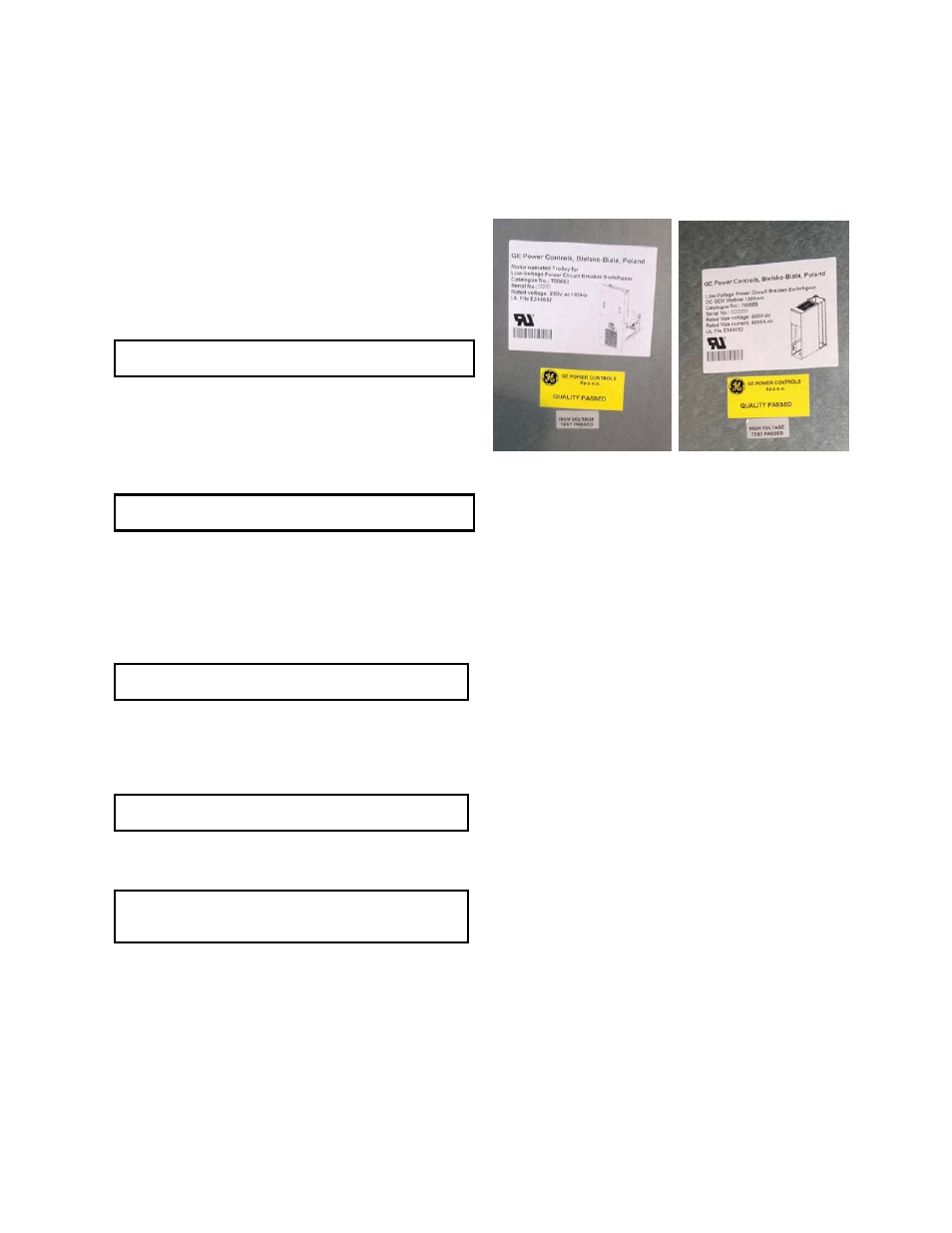
Each module and each trolley undergo High Potential Tests
before shipment. Passing of compete Factory Acceptance Test
sequence is marked by sticker note. See Fig. 61-1.
Fig. 61-1 Quality check markings after FAT tests
If local codes demand this test, or the purchaser wishes to make
high-potential tests, the voltage should not exceed, for the power
circuit, 2.8 kV RMS or 3.9 kV DC and for the control circuit
1.2 kV RMS. Testing procedure is described in Appendix H, Table
H-7.
Grounding Circuit Check
If local codes demand this test, or the purchaser wishes to make
earthing system test, refer to procedure described in Appendix H,
Table H-8.
Minimum current required for checking of grounding connections
is 10 A. Resistance for each measured grounding connection
must be less than 0.1 Ohm.