Installing the breaker, 2 installing gerapid breaker – GE Industrial Solutions DC OEM Module For use with Gerapid DC Circuit Breaker User Manual
Page 13
DC OEM MODULE FOR USE WITH GERAPID CIRCUIT BREAKERS
Chapter 5 Installing the Breaker
2011-04-26 S47183Ee rev.01
Design and specifications are subject to change without notice
13
Installing the Breaker
5-1 General Notes
Before installing, operating, or removing a circuit breaker, refer to
the Gerapid breaker instruction manual S47183De for
preparation, inspection, and test. Check thoroughly for damaged
or loose parts and for any dirt or foreign matter, which may be in
the breaker.
To install the breaker, proceed as follows:
1)
Before installing a breaker, check the contact areas
on each primary disconnect cluster of fingers for foreign
matter that may have accumulated. Clean these areas if
necessary. Be sure that a thin film of the red lubricating
grease “MOBIL GREASE 28” covers the fingers areas before
putting a breaker in the compartment.
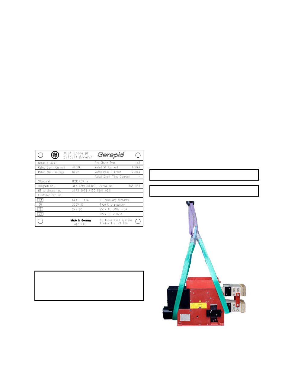
2)
Check to see that the breakers match their respective
trolley and compartment. Each breaker is assigned a serial
number and ratings. These are shown on the breaker’s
nameplate. The breaker may also be identified using the 20-
digit PST catalog number. See Fig 51-1.
Fig. 51-1 Nameplate of Gerapid breaker
Breakers of the same rating are interchangeable in their
equipment compartments, as long as they have the same
accessories equipped.
The trolley design is the same and universal, regardless of the
Gerapid breaker type intend to operate with.
WARNING: A breaker with different rating fit into any of the
trolleys. If the trolley’s rejection interlock does not match the
breaker’s rating, but it does match the compartment’s
rejection interlock, it is possible to rack-in an incorrect breaker
into the compartment. This may lead to serious damages and
could result in death or serious injury for operator!
5-2 Installing Gerapid Breaker
Prior to Installation
Prior to placing a breaker in its intended location on the trolley,
please check following precautions:
1)
Find the foil bag with breaker bolting kit no. 700701
that is attached to the trolley’s platform. Remove it.
2)
Ensure that the breaker is OPEN.
3)
Ensure that arc chute is NOT on the breaker.
4)
Ensure that lifting device can carry ~300 lbs and that
lifting slings are min. 6 ft long.
Installation Procedure
To install the Gerapid circuit breaker, proceed as follows:
1)
Ensure that the lifting frame has been removed from
the trolley. See Fig. 22-2.
2)
Place the lifting slings in position. See Fig. 52-1.
Carefully lift the breaker and place it on the trolley.
3)
Slide in the breaker toward the front of the trolley,
until four attachment bolt holes in platform match the holes in
breaker baseplate. Install bolts provided and tighten with
torque listed in Table D-1. The fixing kit is attached to the
trolley’s platform.
4)
Plug in all connectors to correct terminals at the front
of breaker’s control box. Tight the connectors. See Fig. 52-3.
WARNING: Do not stand under the circuit breaker during the
lifting and transport operations.
NOTE: Do not transport the circuit breaker with arc chute
installed.
Fig. 52-1 Lifting the breaker