GE Industrial Solutions DC OEM Module For use with Gerapid DC Circuit Breaker User Manual
Page 47
DC OEM MODULE FOR USE WITH GERAPID CIRCUIT BREAKERS
APPENDIX H Field Test Procedure.
2011-04-26 S47183Ee rev.01
Design and specifications are subject to change without notice
47
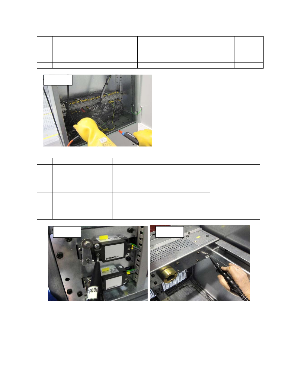
Table H-7 High Potential Tests for control and auxiliary circuits
Step
Starting Status
Check Points
Pass Criteria
3.1
Trolley is at TEST position.
Breaker is OPEN.
Connect all control wires together.
Disconnect all earthing wires.
Apply 3.9 kV DC or 1.2 kV RMS for 60 seconds between
wiring harness and frame.
No flashover.
3.2
END OF PROCEDURE
Table H-8 Grounding Circuit Tests
Step
Starting Status
Check Points
Pass Criteria
4.1 Trolley
WITHDRAWN
a. Check mounting screws of end switches no: 33-
1 / 33-2 / 33-3 / S4F / 33-4 / 33-5,
b. Check door locks of the control compartment,
c. Check end switch S3F under the trolley.
Grounding path resistance,
between main ground bus
and measured point, must
be less 0.1 Ohm.
4.2
Rack-in the trolley into TEST
position.
Connect Secondary Plug (g), Fig. H-
2.
a. Check the motor drive’s housing,
b. Check breaker’s grounding point at –X2:3,
c. Check door locks of the trolley,
d. Check handles at the front of the trolley.
Step 3.1
Step 4.1a
Step 4.1a