Installing the module, 2 module configuration and assembly – GE Industrial Solutions DC OEM Module For use with Gerapid DC Circuit Breaker User Manual
Page 11
DC OEM MODULE FOR USE WITH GERAPID CIRCUIT BREAKERS
Chapter 4 Installing the Module
2011-04-26 S47183Ee rev.01
Design and specifications are subject to change without notice
11
Installing the Module
4-1 General Notes
This chapter contains instructions for installing the GE DC OEM
Module.
CAUTION: Personnel installing this equipment must be
thoroughly familiar with this instruction manual and all articles
of the National Electrical Code applicable to the installation of
this equipment. In addition, all drawings, both mechanical
installation and electrical, must be understood and strictly
followed to prevent damage to the module.
Environmental Requirements
The module as provided is designed for indoor installations only
and should be placed in an indoor area where clean, dry air is free
to circulate around and above it. Since air is taken into the
equipment at the bottom of each section and exhausted at the
top, a location with good airflow must be provided for efficient
operation.
A minimum of 30 inches of clear space above the equipment is
recommended. In order to properly withdraw the trolley there
should be at least 7 foot of space in the front of the module.
NOTE: See Appendix C for sketches concerning layout.
Foundation Requirements
The foundation requirements detailed in this chapter should be
strictly adhered to.
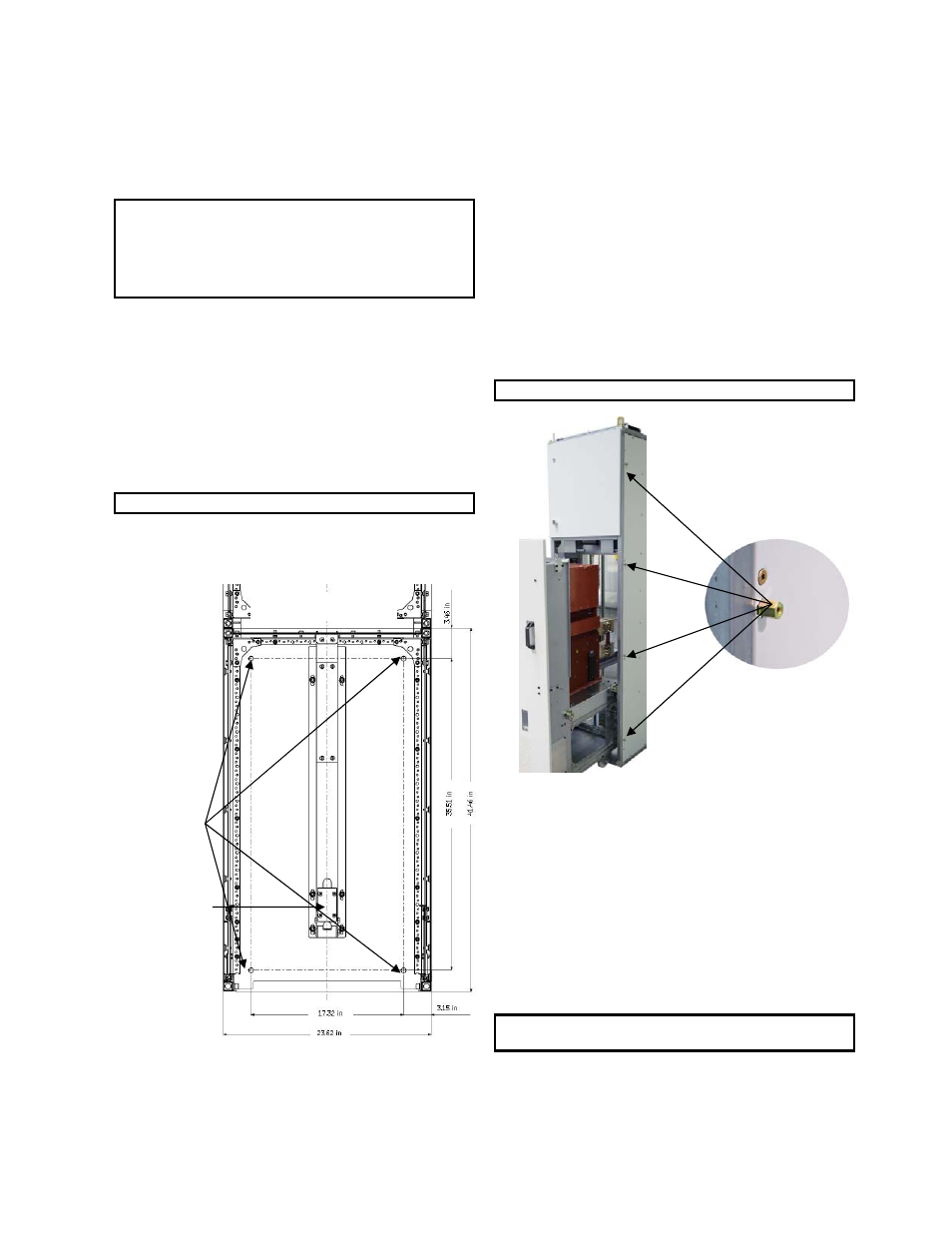
Fig.41-1 Module anchor bolt hole locations
The foundation must be strong enough to prevent sagging due to
the weight of the completed switchgear structure and to
withstand the impact loading caused by the opening of the
breakers under fault conditions. The impact loading is
approximately 1-1/2 times the static load.
The foundation must be flat and level in all planes with maximum
deviation of 0.8 inch at the length of 3 foot. The module should be
anchored to the floor through holes shown on Fig. 41-1 using
7/16” or metric M12 grade 5 steel bolts.
4-2 Module Configuration and Assembly
Multiple Modules Side by Side Assembly
Modules can be connected together to form switchgear lineups.
To bolt two modules together, edge trim strips must be removed.
Special connection spacers must be used and are inserted into 12
hex shaped cut outs visible in the sidewalls. Fig. 42-1 shows the
location of the front 4 connection spacer openings. Location of all
openings and installation tips are shown in Appendix G.
A Module Coupling Kit can be ordered under Cat. No.: 289169.
Each kit consists of 12 Connection spacers, bolts and washers
necessary to connect two adjacent modules.
NOTE: See Appendix D for connection drawings.
Fig. 42-1 Location of front module connection spacers
Module Preparation
Every module is suitable for operating either with manually or
motor operated trolley. Depending on the type of trolley being
utilized, a locking plate in the module may need to be removed:
If motor operated trolley is going to be used with the
Module, remove the locking plate.
If manually operated trolley is going to be used with the
module, keep the locking plate in place
See Fig. 41-1 and Fig. 42-2 to locate locking plate.
NOTE: Look for the yellow warning label placed on the
module’s floor to find bottom guide rail and the plate.
Connection Spacers
12 per side-by-side.
Top View on the floor.
Anchor Points
Use M12 or
7/16” grade 5
bolts.
Locking Plate