General description, 2 summary description, 3 the module – GE Industrial Solutions DC OEM Module For use with Gerapid DC Circuit Breaker User Manual
Page 8
DC OEM MODULE FOR USE WITH GERAPID CIRCUIT BREAKERS
Chapter 4 Installing the Module
8
Design and specifications are subject to change without notice
S47183Ee rev.01 2011-04-26
General Description
3-1 General Notes
This section contains a description of the GE DC OEM Module and
Trolley for use with Gerapid high speed DC circuit breaker. It also
describes the functions of the electrical and mechanical systems.
3-2 Summary Description
The DC OEM Module is an individual, freestanding, metal-enclosed
switchgear section, designed to be used in conjunction with the
withdrawable trolley, containing a Gerapid circuit breaker,
auxiliary contacts, primary finger clusters and secondary
disconnect.
Ratings
The module is designed to be used on DC systems operating up to
800VDC and 6000A continuous.
The module is available in two continuous current ratings:
4000A for use with 2500A and 4000A Gerapid breaker,
6000A for use with 5000A and 6000A Gerapid breaker,
NOTE: See Appendix “F” for complete ratings of the Module
and the breaker.
Interlocks
Module and trolley are equipped with variety of safety interlocks
that minimize risk of incorrect operations. The following interlocks
are incorporated into the module and trolley:
Positive Interlock preventing movement of the trolley to or
from CONNECTED position when breaker is closed.
Negative Interlock preventing breaker closing unless the
trolley is in CONNECTED or TEST position.
Access Interlock – ensures breaker opening before any
manual operations.
Secondary Control Interlock preventing movement of the
trolley from TEST position to CONNECTED position unless
secondary disconnect is connected. The same interlock
prevents the trolley from being fully withdrawn from the
module unless the secondary disconnect is unplugged.
Breaker Disconnected Padlock Provisions allows padlocking
the trolley in DISCONNECTED position.
Control Compartment Padlock Provisions allows for
padlocking of the controls compartment door.
Rejection Interlock prevents trolley coded for particular
breaker current rating from being inserted into the module
that is coded to different rating.
Shutter Safety Padlock allows padlocking of the safety
shutters in closed position.
Accessories
Several accessories are available with the module and the trolley
for user convenience:
Side Covers for cable compartment,
Crank Handle for trolley racking operations,
Cable Channel connectors and covers,
Attachment Hardware Kits for different components,
Hinges for user furnished compartment doors,
NOTE: See Appendix “G” for full list of accessories, their codes
and illustrations.
NOTE: Detailed description of all accessories functions is given
in Chapter 7.
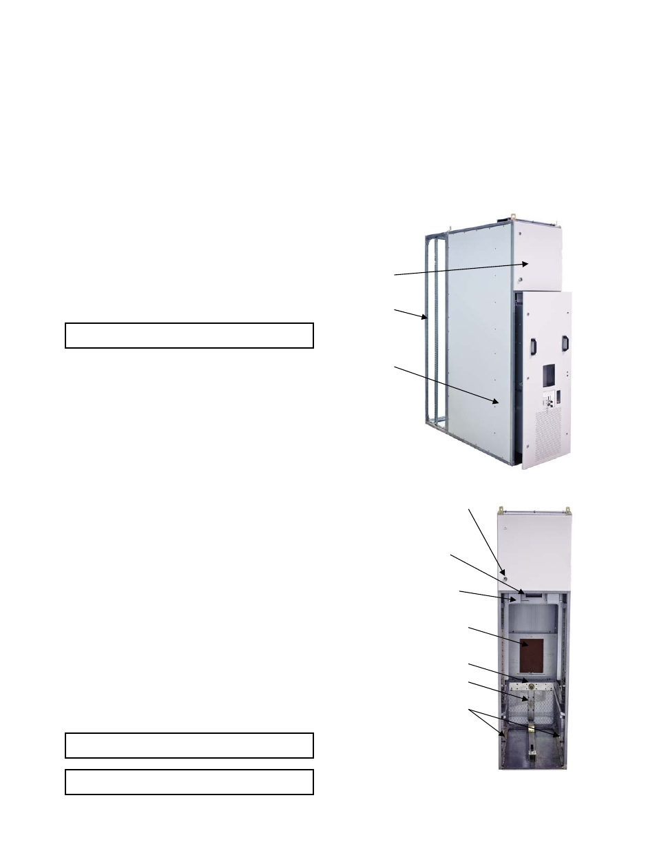
3-3 The Module
Breaker Compartment
The module is metal-enclosed construction, and consists of the
front breaker compartment, upper controls compartment and
rear cable compartment. Fig. 33-1 shows the location of the
module compartments.
Dead-front, drawout circuit breaker compartment is a standard
construction feature with all modules. The breaker compartment
door remains closed and latched while the breaker is racked out
from the CONNECTED position through TEST position, to the
DISCONNECTED position. See chapter 7.
Fig. 33-1 Front view of the Module with Trolley inside
Fig. 33-2 Front view of the module
Secondary Control Interlock
Control Compartment
Padlock Provisions
Control
Compartment
Cable
Compartment
Breaker
Compartment
Secondary Disconnect
Primary Disconnect Shutters
In front of Primary Stabs
Racking Drive Socket
Grounding Circuit Stab
Rejection Interlocks