GE Industrial Solutions DC OEM Module For use with Gerapid DC Circuit Breaker User Manual
Page 20
DC OEM MODULE FOR USE WITH GERAPID CIRCUIT BREAKERS
Chapter 7 Operating the Module
20
Design and specifications are subject to change without notice
S47183Ee rev.01 2011-04-26
1. CONNECTED position – Primary Disconnects and
Secondary Disconnect in full contact, breaker ready for normal
operation. Position Interlock, see Fig. 73-1, keeps the trolley in
this position.
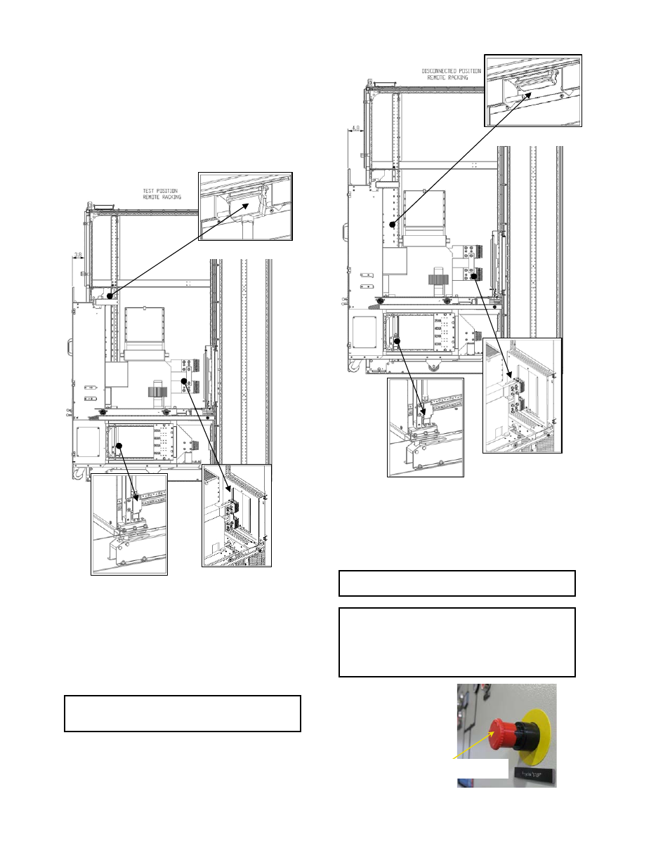
2. TEST position - Primary Disconnect open and separated by
a safe distance with shutters closed. The Secondary
Disconnect is in full contact. The Trolley is withdrawn ~4 inches
and locked by Position Interlock. See Fig. 72-3.
Fig. 73-2 TEST position for remote racking trolley
3. DISCONNECTED position - Primary Disconnects open and
separated by a safe distance with shutters closed. Secondary
Disconnect is open. Trolley is withdrawn ~5 inches. See Fig. 72-
3.
4. WITHDRAWN position – Trolley outside of the module.
NOTE: Remote racking-operations require control voltage
and control commands to be provided. See Appendix E for
electrical circuit drawings.
Fig. 73-3 DISCONNECTED position for remote racking
trolley.
Remote Rack–In Procedure.
NOTE: Crank Handle is necessary for completing racking
operations. Crank Handle has to be ordered separately.
WARNING: EMERGENCY RACKING STOP circuit (Y58 Y59)
must be wired to a pushbutton (furnished by OEM). It is
recommended the STOP PB be installed on the control
compartment door. See example Fig. 73-4.
Use this pushbutton for immediate interruption of racking
operation and stop the trolley regardless of its position.
Fig. 73-4 EMERGENCY STOP pushbutton (by OEM)
Secondary Disconnect
Primary Disconnects
Position Interlock
Secondary Disconnect
Primary Disconnects
Position Interlock
EMERGENCY RACKING STOP