GE Industrial Solutions DC OEM Module For use with Gerapid DC Circuit Breaker User Manual
Page 12
DC OEM MODULE FOR USE WITH GERAPID CIRCUIT BREAKERS
Chapter 4 Installing the Module
12
Design and specifications are subject to change without notice
S47183Ee rev.01 2011-04-26
Fig. 42-2 Locking Plate
Module Rejection Interlock
OEM must configure the rejection interlock in the module, before
its usage. Four different configurations are possible: 2500A,
4000A, 5000A or 6000A. In the module, rejection markers must be
screwed in place aligned with all current ratings except the one
that module is dedicated to. This should be done on the right and
left side of the module.
Fig. 42-3 illustrates a correctly configured module rejection
Interlock for a 2500A rated Gerapid breaker. Rejection markers
must be fixed on both right and left sides of the breaker
compartment, aligned with ratings: 4000A, 5000A and 6000A.
Fig.42-3 Rejection interlock set up for rating of 2500A
NOTE: Always verify that the rating on rejection interlock is not
higher that the module rated current.
NOTE: Always configure rejection interlock on both sides of the
module breaker compartment.
Main Busbars Connection
Module primary terminals are silver plated copper and are
suitable to connect to copper bus bars as per IEEE Std. C37.14
Table 6. Connected bus bars should not have cross sections less
that recommend in Table 6.
Gerapid circuit breakers are not polarized. Therefore the load and
the supply line can be connected to either top or bottom terminal.
See Fig. 33-4 for primary terminals views.
NOTE: See Appendix B for primary terminals drawings and
recommend bus bar dimension.
Ground Bus Connection
Ground bus connection terminal is located at the bottom of the
module in the cable compartment. See Fig.
33-4. Circuit
connections to a ground bus are made so that it is not necessary
to open-circuit the ground bus to remove any connection made
to the ground bus. Ground connections are provided for all
removable elements to ensure that the frame and mechanism are
grounded until the primary circuit is disconnected and the
removable element is moved a safe distance.
NOTE: See Appendix B for ground terminal drawings.
Connecting Secondary Controls
Secondary disconnect plug in the module is pre-wired with the
harness going into control compartment. All wires that should be
used by OEM for completing the module and breaker control are
numbered and accessible inside the Control Compartment.
NOTE: See Appendix E for electrical schemes for connections.
NOTE: See Appendix A for control compartment dimensions.
All trolley control commands and supply connections are also
available thru the harness in the Control Compartment.
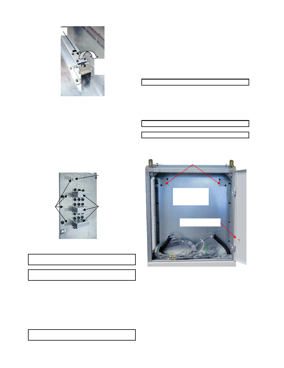
Fig.42-4 Control compartment
Device mounting on control compartment door
Control compartment’s door should be removed before making
any cutouts. To remove the door, open and remove grounding
connection. Lift the door up until the pins are free from hinges.
All auxiliary devices can be attached to the mounting plate
provided at the back of the control compartment. However it is
recommend prefabricating a separate metal sheet and installing
it in the control compartment using frame supports.
There are two cover plates that provide access to the top
mounted wire way (cable channel). Remove the covers to use
them. See Fig. 42-4.
Locking Plate
Remove for motor
operated trolley !
Installed Breaker
Rejection Markers
Rating
Markers
Components
Mounting Plate
Grounding Stud
Top mounted wire way
access covers