Operating the module, 1 mechanisms and interlocks – GE Industrial Solutions DC OEM Module For use with Gerapid DC Circuit Breaker User Manual
Page 16
DC OEM MODULE FOR USE WITH GERAPID CIRCUIT BREAKERS
Chapter 7 Operating the Module
16
Design and specifications are subject to change without notice
S47183Ee rev.01 2011-04-26
Operating the Module
7.1 Mechanisms and Interlocks
Racking Mechanism
The racking mechanism is designed for moving the trolley
between two (2) positions, TEST and CONNECTED. Clockwise
rotation of the racking shaft, Fig. 71-1, results in Trolley
movement toward the CONNECTED position. Counterclockwise
rotation of the racking mechanism results in trolley movement
from the CONNECTED to the TEST position.
Fig. 71-1 Racking system
The racking mechanism can be manually or remotely
operated, closed-door drawout, designed to prevent over-
travel, and equipped with guides for alignment of the breaker
in the module. The Crank Handle has a torque clutch. See
Fig. 71-2. This clutch protects the racking system against
damages caused by applying excessive force when Trolley is in
CONNECTED position.
Fig 71-2 Crank Handle
An indicator is provided to show breaker position within the
compartment. See Fig. 71-3. The indicator is visible from the
exterior of the switchgear
.
Fig. 71-3 Position Indicator
Trolley is equipped with integral wheels for moving the trolley
in and out of a cubicle and sized to carry the weight without
deforming or cutting into the concrete surface. The wheels roll,
but not slide, and guide the trolley to correctly align and
engage the racking mechanism.
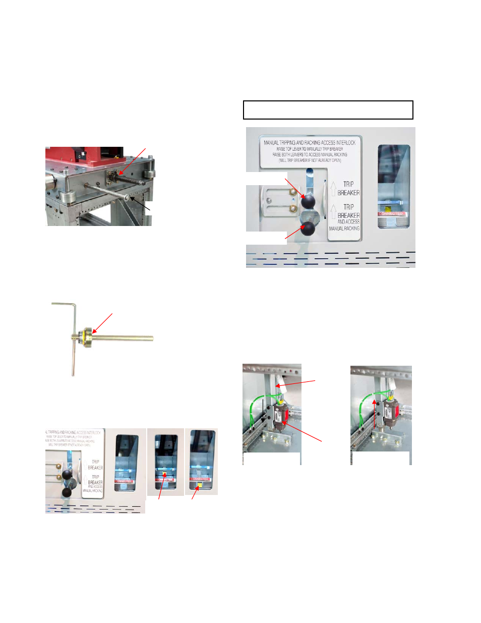
Access Interlocks
Front door Access Interlock, see Fig. 71-4, ensures tripping of
the breaker before the Crank Handle can be inserted for
racking. Lifting up of the Trip Lever causes breaker to trip open,
and additionally enable access to manual racking slot.
NOTE: The Access Lever is locked in lower position when
the breaker is closed.
Fig. 71-4 Front door Access Interlock
Trip Lever is mechanically coupled with a vertical interlock
under the trolley. This interlock mechanically locks the trolley in
TEST or CONNECTD position.
When the Tri Lever is lifted up, the “Crank Lock” stop switch
(S3F) electrically cuts-off the closing circuit of the breaker and
blocks remote racking. This ensures no remote command
activates the trolley or closes the breaker with the Crank
Handle is inserted. See Fig. 71 5 and wiring circuit in Appendix
D.
Fig. 71-5 Locking rod with S3F end switch “Crank Lock”
Secondary Control Interlock
Secondary Disconnect consist of a receptacle installed in the
stationary cell and removable plug, which is a part of the
trolley. See Fig. 71-6. This disconnect is equipped with Rack-in
Interlock preventing movement of the trolley from TEST
position to CONNECTED position unless Secondary Disconnect
is connected. Rack-out Interlock prevents the trolley from
being fully withdrawn from the Module unless the secondary
disconnect is unplugged. See Fig. 71-6.
After removing the plug, both interlocks move to the right and
reset. This enables withdrawal operation and blocks rack-in
operation as shown at Fig. 71-7.
Racking Shaft
Indicator Shaft
Clutch
TEST CONNECTED
Trip Lever
Access Lever
Lower position
Upper position
-S3F stop
switch
Operating
Rod