4 operate the breaker – GE Industrial Solutions DC OEM Module For use with Gerapid DC Circuit Breaker User Manual
Page 21
DC OEM MODULE FOR USE WITH GERAPID CIRCUIT BREAKERS
Chapter 7 Operating the Module
2011-04-26 S47183Ee rev.01
Design and specifications are subject to change without notice
21
1.
Trolley WITHDRAWN. Push trolley toward the module
until it stops at DISCONNECTED position.
2.
Open the trolley’s door and install Secondary
Disconnect.
NOTE: Use the Door Key provided to open all Door Locks
and release Door Interlock. See Fig. 73-4.
NOTE: Make sure that Receptacle Snap Lock is engaged.
3.
Lift up the Access Lever (Fig. 71-4) and push the
trolley in further until racking shaft (Fig. 71-1) couples with
socket (Fig. 71-8).
NOTE: S4F contact should indicate the coupling position if
connected (Y64 Y65) to any external indication device.
4.
Insert Crank Handle into the Access Console slot,
Fig. 72-4 and rotate Crank Handle clockwise until trolley
reaches TEST position.
NOTE: TEST position is indicated by Position Indicator,
(Fig. 71-3) or by indication of switch 33-4 (Fig. 71-9).
5.
Remove Crank Handle. Push the Trip Lever down,
(Fig. 71-4), making sure that both levers of the Access
Console are in their maximum lower positions.
NOTE: If the Access Lever is not at its maximum lower
position, closing of the breaker or remote rack-in will not
be possible.
6.
Use RACK BREAKER-IN command (Y60 Y61) to start
motor for rack in operation. Trolley will stop at
CONNECTED position.
WARNING: Use EMERGENCY STOP pushbutton in case of
emergency situation. See Fig.73-4.
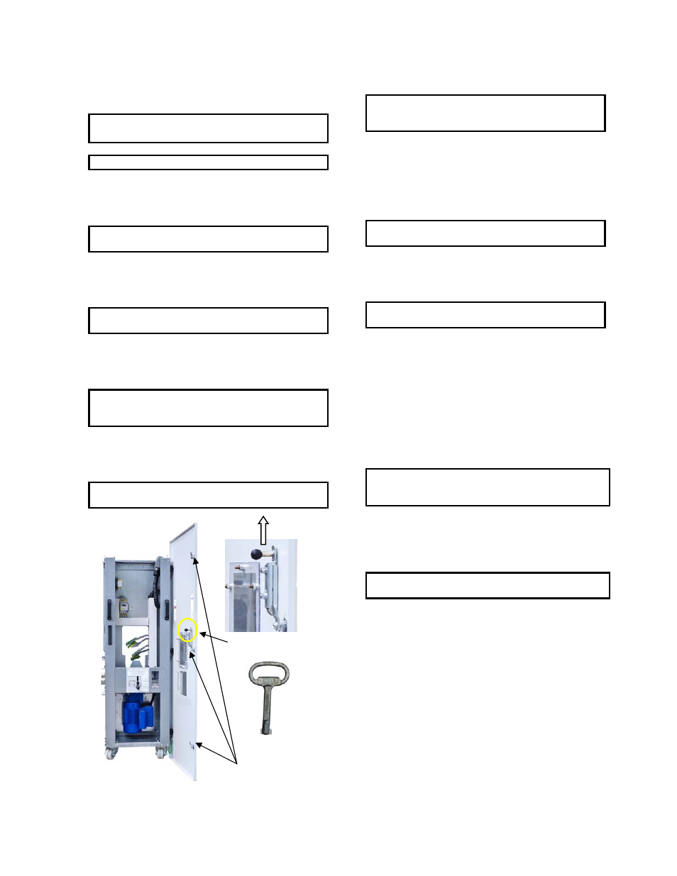
Fig. 73-4 Door locks
Manual Rack-Out Procedure.
NOTE: Crank Handle is necessary for completing of
racking operations. Crank Handle has to be ordered
separately.
1. Trolley CONNECTED. Open the breaker either using
OPEN command or pulling up the Trip Lever (Fig. 71-
4).
2. Use RACK BREAKER-OUT command (Y62 Y63) to start
motor for rack out operation. Trolley will stop at TEST
position.
NOTE: TEST position is indicated by Position Indicator,
(Fig. 71-3) or by indication of switch 33-4 (Fig. 71-9).
3. Open the trolley’s door and disconnect the
Secondary Disconnect. Hang it on the frame to the
right (Fig. 71-7).
NOTE: Use the Door Key to open all Door Locks and
release Door Interlock. See Fig. 73-4.
4. Lift up the Access Lever (Fig. 71-4) and insert Crank
Handle. Rotate Crank Handle counterclockwise until
trolley stops. Now the trolley is in the DISCONNECTED
position.
5. Remove Crank Handle. Lift up the Access Lever
(Fig. 71-4) and pull the trolley out from the module.
7.4 Operate the breaker.
Gerapid circuit breakers can be operated electrically and
manually.
NOTE: Manual CLOSE operation at the breaker is possible
only at WITHDRAWN position of the trolley. Manual closing
should only be performed for maintenance.
Manual OPEN operation at CONNECTED or TEST positions is
possible by means of Trip Lever. For maintenance purposes
breaker can be operated by means of dedicated hand lever at
WITHDRAWN position.
NOTE: See User Manual S47183De for breaker operation
details and accessories.
All electric control commands and signals are wired thru
available harness (Y01 Y54). See Appendix E for details of
available commands and signals.
Lift to release
Door Locks
Door Key
Door Interlock