Appendix h – field test procedure, Connecting control commands for testing – GE Industrial Solutions DC OEM Module For use with Gerapid DC Circuit Breaker User Manual
Page 43
DC OEM MODULE FOR USE WITH GERAPID CIRCUIT BREAKERS
APPENDIX H Field Test Procedure.
2011-04-26 S47183Ee rev.01
Design and specifications are subject to change without notice
43
APPENDIX H – Field Test Procedure
This Appendix describes full recommended procedure for Field Testing of DC OEM Module equipped with Gerapid DC Circuit Breaker.
The description consists of four chapters:
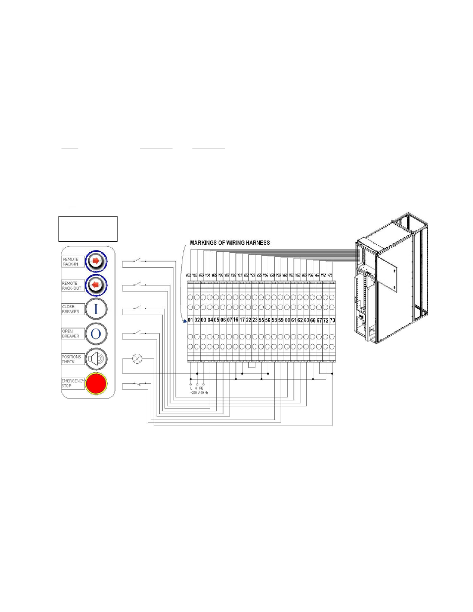
Connecting control commands to the module. See Fig. H-1
Testing the module with Remote Racking. See Table H-3.
Testing the module with Manual Racking. See Table H-4.
High potential test (optional). See Table H-6.
Connecting control commands for testing
Following control commands are available for OEM wiring:
Name
Wire Points
Description
RACK BREAKER-IN
(Y60-Y61)
Moves trolley from TEST to CONNECTED position.
RACK BREAKER-OUT
(Y62-Y63)
Moves trolley from CONNECTED to TEST position.
GERAPID SOLENOID CLOSE– (Y04-Y05)
Closes Gerapid breaker, possible only in TEST or CONNECTED positions.
GERAPID OPEN
(Y06-Y07)
Opens Gerapid breaker, possible only in TEST or CONNECTED positions.
POSITIONS CHECK
(Y67/Y73)
Signals when trolley reaches TEST or CONNECTED position.
EMERGENCY RACKING STOP (Y58-Y59)
Immediately stops the trolley regardless of position.
Fig. H-1 Wiring diagram for connection of control functions for the module.
Typical external
controls, furnished
by OEM.