A series, Sample packets – GE Industrial Solutions A Series Lighting Control Panelboards Modbus Register Map User Manual
Page 25
A Series
®
Lighting Controller Modbus Register Map
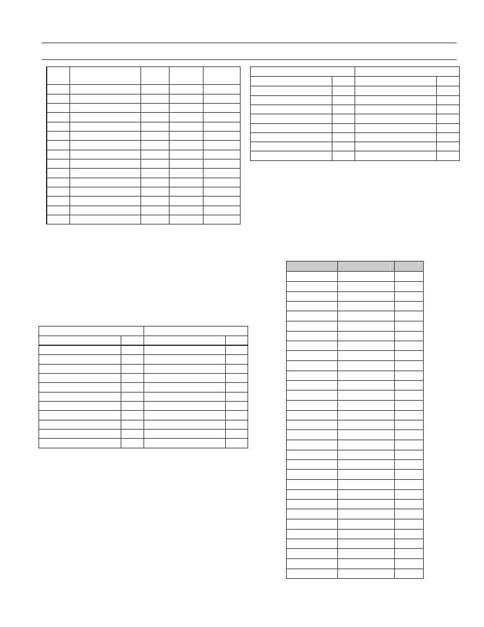
Physical Output Registers-Binary Outputs (BO)
19
Reg.
Contents
Type
Format
BO
Instance
252 BO52 OutOfService
RW
ON/OFF
52
253 BO53 OutOfService
RW
ON/OFF
53
254 BO54 OutOfService
RW
ON/OFF
54
255 BO55 OutOfService
RW
ON/OFF
55
256 BO56 OutOfService
RW
ON/OFF
56
257 BO57 OutOfService
RW
ON/OFF
57
258 BO58 OutOfService
RW
ON/OFF
58
259 BO59 OutOfService
RW
ON/OFF
59
260 BO60 OutOfService
RW
ON/OFF
60
261 BO61 OutOfService
RW
ON/OFF
61
262 BO62 OutOfService
RW
ON/OFF
62
263 BO63 OutOfService
RW
ON/OFF
63
264 BO64 OutOfService
RW
ON/OFF
64
265 BO65 OutOfService
RW
ON/OFF
65
266 BO66 OutOfService
RW
ON/OFF
66
Table 30. List of physical output registers (OutOfService).
Sample Packets
The following are examples of requests to specific groups
of output registers.
Write to Output Reg201
Table 31 shows the result of a write request to output
OutOfService Reg201 (Function 5 Single Write, BO1 in
map).
Request
Response
Field Name
Hex Field Name
Hex
Device Address
01
Device Address
01
Function
0F
Function
0F
Register Address Hi
DB Register Address Hi
DB
Register Address Lo
00
Register Address Lo
00
Quantity of Outputs Hi
00
Quantity of Outputs Hi
00
Quantity of Outputs Lo
0A Quantity of Outputs Lo
0A
Byte Count
02
Packet CRC Hi
Output Value Hi
CD Packet CRC Lo
Output Value Lo
03
Packet CRC Hi
Packet CRC Lo
Table 31. Sample packet for multiple write to output Reg220–Reg229.
Multiple Write Output Reg220–Reg229
Table 32 shows the result of a multiple write to BO
OutOfService Reg220–229 (Function 15 Multiple Write,
BO 20–29 in map).
Note that the Hi byte 0xCD addresses outputs 27–20, with
the least-significant bit addressing the lowest output 20
and the most-significant bit addressing the highest output
27. The Lo byte 03 addresses outputs 29–28, with the least-
significant bit addressing the lowest output 28. Unused
bits in the last data byte are padded with zeros
Request
Response
Field Name
Hex Field Name
Hex
Device Address
01
Device Address
01
Function
05
Function
05
Register Address Hi
00
Register Address Hi
00
Register Address Lo
C8 Register Address Lo
C8
Output Value Hi
FF
Output Value Hi
FF
Output Value Lo
00
Output Value Lo
00
Packet CRC Hi
Packet CRC Hi
Packet CRC Lo
Packet CRC Lo
Table 32. Sample packet for write to output Reg201.
Binary Output (BO) Object – (Registers 2001 – 3260)
Each Binary Output object contains 12 properties that are
exposed to MODBUS. These object properties are
writable via Function Codes 6 & 16 and readable by
Function Code 3. Writes to the BO Value occur at
BACnet Priority Level 5 (Critical Equipment Control).
Table 33 shows list of registers associated with B01-B066.
Register
BO Object
Type
2001 – 2018
BO1
RW
2019 – 2036
BO2
RW
2037 – 2054
BO3
RW
2055 – 2072
BO4
RW
2073 – 2090
BO5
RW
2091 – 2108
BO6
RW
2109 – 2126
BO7
RW
2127 – 2144
BO8
RW
2145 – 2162
BO9
RW
2163 – 2180
BO10
RW
2181 – 2198
BO11
RW
2199 – 2216
BO12
RW
2217 – 2234
BO13
RW
2235 – 2252
BO14
RW
2253 – 2270
BO15
RW
2271 – 2288
BO16
RW
2289 – 2306
BO17
RW
2307 – 2324
BO18
RW
2325 – 2342
BO19
RW
2343 – 2360
BO20
RW
2361 – 2378
BO21
RW
2379 – 2396
BO22
RW
2397 – 2414
BO23
RW
2415 – 2432
BO24
RW
2433 – 2450
BO25
RW
2451 – 2468
BO26
RW
2469 – 2486
BO27
RW
2487 – 2504
BO28
RW
2505 – 2522
BO29
RW
2523 – 2540
BO30
RW
2541 – 2558
BO31
RW