Physical output registers (outofservice), A series – GE Industrial Solutions A Series Lighting Control Panelboards Modbus Register Map User Manual
Page 24
A Series
®
Lighting Controller Modbus Register Map
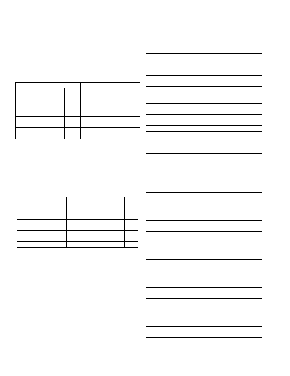
Physical Output Registers-Binary Outputs (BO)
18
Read Coil Status of BO Reg2 to Reg19
Table 28 shows the result of a request to read the coil
status of BO Reg2–Reg19 (Function 1, BO2–19 in map).
Note that the status of outputs 19–18 is shown as the byte
value 0x03 or binary 0000 0011 and output 18 is the LSB.
The six remaining high-order bits are zero filled.
Request
Response
Field Name
Hex
Field Name
Hex
Device Address
01
Device Address
01
Function
01
Function
01
Register Address Hi
00
Byte Count
03
Register Address Lo
01
Output Status 9–2
AC
Quantity of Outputs Hi
00
Output Status 17–10
0A
Quantity of Outputs Lo
12
Output Status 19–18
03
Packet CRC Hi
Packet CRC Hi
Packet CRC Lo
Packet CRC Lo
Table 28. Sample packet for coil status of BO Reg2 to Reg19.
Read Coil Status of BO Reg62 to Reg66
Table 29 shows the result of a request to read the coil
status of BO Reg62–Reg66 (Function 1, BO62–66). Note
that the status of outputs 66–62 is shown as the byte value
0x37 or binary 0001 0111 and output 62 is the LSB. The
remaining two high-order bits are zero filled.
Request
Response
Field Name
Hex Field Name
Hex
Device Address
01
Device Address
01
Function
01
Function
01
Register Address Hi
00
Byte Count
03
Register Address Lo
3D Output Status 66–62
17
Quantity of Outputs Hi
00
Packet CRC Hi
Quantity of Outputs Lo
05
Packet CRC Lo
Packet CRC Hi
Packet CRC Lo
Table 29. Sample packet for coil status of BO Reg62 to Reg 66.
The output values are
Reg62: BO62 Value – ON
Reg63: BO63 Value – ON
Reg64: BO64 Value – ON
Reg65: BO65 Value – OFF
Reg66: BO66 Value – ON
Physical Output Registers
(OutOfService)
Actual value registers start at 201, commanded by
Function Code 01, 05, or 15 and mapped to Binary
Outputs (BO) 1–66. The address space is reserved to 900.
The value in the register represents the Binary Output’s
OutOfService value. A value of 1 corresponds to manual
mode, 0 to auto mode.The physical output registers
(OutOfService) are listed in Table 30.
Reg.
Contents
Type
Format
BO
Instance
201
BO1 OutOfService
RW
ON/OFF
01
202
BO2 OutOfService
RW
ON/OFF
02
203
BO3 OutOfService
RW
ON/OFF
03
204
BO4 OutOfService
RW
ON/OFF
04
205
BO5 OutOfService
RW
ON/OFF
05
206
BO6 OutOfService
RW
ON/OFF
06
207
BO7 OutOfService
RW
ON/OFF
07
208
BO8 OutOfService
RW
ON/OFF
08
209
BO9 OutOfService
RW
ON/OFF
09
210 BO10 OutOfService
RW
ON/OFF
10
211 BO11 OutOfService
RW
ON/OFF
11
212 BO12 OutOfService
RW
ON/OFF
12
213 BO13 OutOfService
RW
ON/OFF
13
214 BO14 OutOfService
RW
ON/OFF
14
215 BO15 OutOfService
RW
ON/OFF
15
216 BO16 OutOfService
RW
ON/OFF
16
217 BO17 OutOfService
RW
ON/OFF
17
218 BO18 OutOfService
RW
ON/OFF
18
219 BO19 OutOfService
RW
ON/OFF
19
220 BO20 OutOfService
RW
ON/OFF
20
221 BO21 OutOfService
RW
ON/OFF
21
222 BO22 OutOfService
RW
ON/OFF
22
223 BO23 OutOfService
RW
ON/OFF
23
224 BO24 OutOfService
RW
ON/OFF
24
225 BO25 OutOfService
RW
ON/OFF
25
226 BO26 OutOfService
RW
ON/OFF
26
227 BO27 OutOfService
RW
ON/OFF
27
228 BO28 OutOfService
RW
ON/OFF
28
229 BO29 OutOfService
RW
ON/OFF
29
230 BO30 OutOfService
RW
ON/OFF
30
231 BO31 OutOfService
RW
ON/OFF
31
232 BO32 OutOfService
RW
ON/OFF
32
233 BO33 OutOfService
RW
ON/OFF
33
234 BO34 OutOfService
RW
ON/OFF
34
235 BO35 OutOfService
RW
ON/OFF
35
236 BO36 OutOfService
RW
ON/OFF
36
237 BO37 OutOfService
RW
ON/OFF
37
238 BO38 OutOfService
RW
ON/OFF
38
239 BO39 OutOfService
RW
ON/OFF
39
240 BO40 OutOfService
RW
ON/OFF
40
241 BO41 OutOfService
RW
ON/OFF
41
242 BO42 OutOfService
RW
ON/OFF
42
243 BO43 OutOfService
RW
ON/OFF
43
244 BO44 OutOfService
RW
ON/OFF
44
245 BO45 OutOfService
RW
ON/OFF
45
246 BO46 OutOfService
RW
ON/OFF
46
247 BO47 OutOfService
RW
ON/OFF
47
248 BO48 OutOfService
RW
ON/OFF
48
249 BO49 OutOfService
RW
ON/OFF
49
250 BO50 OutOfService
RW
ON/OFF
50
251 BO51 OutOfService
RW
ON/OFF
51