Physical output registers (coils), A series, Sample packets – GE Industrial Solutions A Series Lighting Control Panelboards Modbus Register Map User Manual
Page 23
A Series
®
Lighting Controller Modbus Register Map
Physical Output Registers-Binary Outputs (BO)
17
Physical Output Registers (Coils)
Lighting controller supports up to 66 breaker outputs
(BO). Actual value registers start at 1, commanded by
Function Codes 01, 05, and 15 and are mapped to Binary
Outputs (BO) 1–66. The value in the register represents
the Binary Output’s present value when read. Writes go to
priority level 5. Writes will only be accepted if the
‘OutOfService’ flag is set for that particular output.
A value of 1 represents ON and a value of 0 represents
OFF.
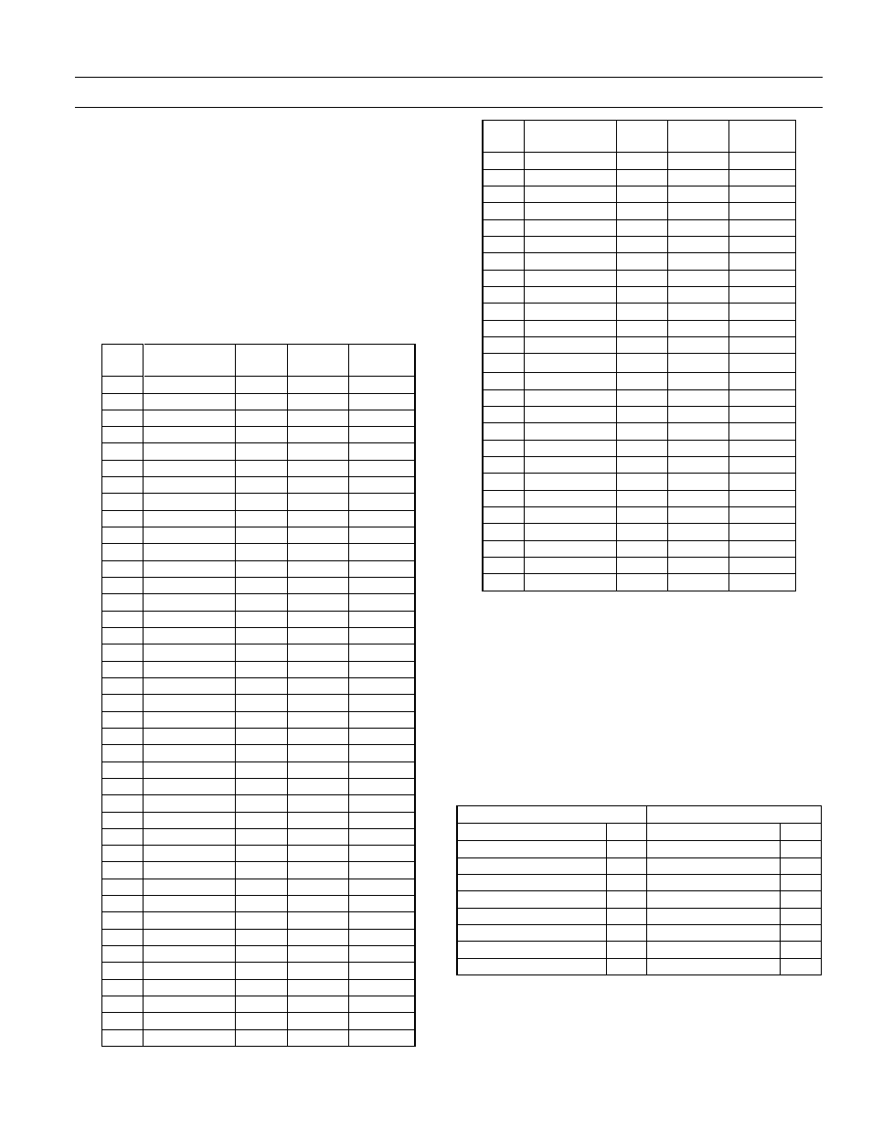
The physical output registers (coils) are listed in Table 26.
Reg.
Contents
Type
Format
BO
Instance
1
BO1 Value
RW
Bit
01
2
BO2 Value
RW
Bit
02
3
BO3 Value
RW
Bit
03
4
BO4 Value
RW
Bit
04
5
BO5 Value
RW
Bit
05
6
BO6 Value
RW
Bit
06
7
BO7 Value
RW
Bit
07
8
BO8 Value
RW
Bit
08
9
BO9 Value
RW
Bit
09
10
BO10 Value
RW
Bit
10
11
BO11 Value
RW
Bit
11
12
BO12 Value
RW
Bit
12
13
BO13 Value
RW
Bit
13
14
BO14 Value
RW
Bit
14
15
BO15 Value
RW
Bit
15
16
BO16 Value
RW
Bit
16
17
BO17 Value
RW
Bit
17
18
BO18 Value
RW
Bit
18
19
BO19 Value
RW
Bit
19
20
BO20 Value
RW
Bit
20
21
BO21 Value
RW
Bit
21
22
BO22 Value
RW
Bit
22
23
BO23 Value
RW
Bit
23
24
BO24 Value
RW
Bit
24
25
BO25 Value
RW
Bit
25
26
BO26 Value
RW
Bit
26
27
BO27 Value
RW
Bit
27
28
BO28 Value
RW
Bit
28
29
BO29 Value
RW
Bit
29
30
BO30 Value
RW
Bit
30
31
BO31 Value
RW
Bit
31
32
BO32 Value
RW
Bit
32
33
BO33 Value
RW
Bit
33
34
BO34 Value
RW
Bit
34
35
BO35 Value
RW
Bit
35
36
BO36 Value
RW
Bit
36
37
BO37 Value
RW
Bit
37
38
BO38 Value
RW
Bit
38
39
BO39 Value
RW
Bit
39
40
BO40 Value
RW
Bit
40
Reg.
Contents
Type
Format
BO
Instance
41
BO41 Value
RW
Bit
41
42
BO42 Value
RW
Bit
42
43
BO43 Value
RW
Bit
43
44
BO44 Value
RW
Bit
44
45
BO45 Value
RW
Bit
45
46
BO46 Value
RW
Bit
46
47
BO47 Value
RW
Bit
47
48
BO48 Value
RW
Bit
48
49
BO49 Value
RW
Bit
49
50
BO50 Value
RW
Bit
50
51
BO51 Value
RW
Bit
51
52
BO52 Value
RW
Bit
52
53
BO53 Value
RW
Bit
53
54
BO54 Value
RW
Bit
54
55
BO55 Value
RW
Bit
55
56
BO56 Value
RW
Bit
56
57
BO57 Value
RW
Bit
57
58
BO58 Value
RW
Bit
58
59
BO59 Value
RW
Bit
59
60
BO60 Value
RW
Bit
60
61
BO61 Value
RW
Bit
61
62
BO62 Value
RW
Bit
62
63
BO63 Value
RW
Bit
63
64
BO64 Value
RW
Bit
64
65
BO65 Value
RW
Bit
65
66
BO66 Value
RW
Bit
66
Table 26. List of physical output registers (coils).
Sample Packets
The following are examples of packets generated by
requests for specific groups of outputs.
Read Coil Status of BO Reg2 to Reg17
Table 27 shows the result of a request to read the coil
status of BO Reg2–Reg17 (Function 1, BO2–17 in map).
Note that the status of outputs 9–2 is shown as the byte
value 0xAC or binary 1010 1100 and output 2 is the LSB.
Request
Response
Field Name
Hex
Field Name
Hex
Device Address
01
Device Address
01
Function
01
Function
01
Register Address Hi
00
Byte Count
02
Register Address Lo
01
Output Status 9–2
AC
Quantity of Outputs Hi
00
Output Status 17–10 0A
Quantity of Outputs Lo
10
Packet CRC Hi
Packet CRC Hi
Packet CRC Lo
Packet CRC Lo
Table 27. Sample packet for coil status of BO Reg2 to Reg17.