A series – GE Industrial Solutions A Series Lighting Control Panelboards Modbus Register Map User Manual
Page 20
A Series
®
Lighting Controller Modbus Register Map
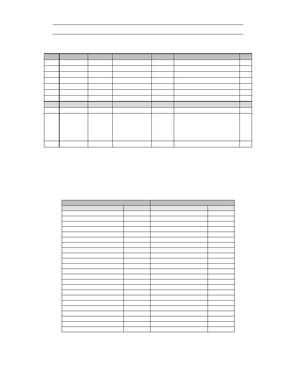
Physical Input Registers-Analog Input (AI)
14
Offset Modbus Regs DB size
Property
Format
Range
Type
0
1001
Bit
OutOfService
Int
0 – 1
RW
1
1002
FLOAT Hi Value *
0 – 65535
RW
2
1003
FLOAT Lo
0 – 65535
RW
3
1004
FLOAT Hi Calibration
0 – 65535
RW
4
1005
FLOAT Lo
0 – 65535
RW
5
1006
Bit
Commissioned
Int
0 – 1
RW
6
1007
WORD
Reliability
Int
Enum
R
Configuration Ref.
7
1008
WORD
Object Type
176 [AIC]
RW
8
1009
WORD
Object Instance
1 – 65535
1 = Photodiode Linear
2 = Photoconductive
3 = Photodiode Linear (Inverse)
4 = Photoconductive (Inverse)
RW
9 registers per AI
Table 21. Property of AI1 object
Note:
•
AIC reference registers 1008 and 1009 must be written in a single write using Function
16.
•
Analog Input Configuration (AIC) object type in Hexadecimal is <00B0>
Sample packets
Table 22 indicates the result of read request for AI1 object
Request
Response
Field Name
(Hex)
Field Name
(Hex)
Device Address
01
Device Address
01
Function
03
Function
03
Starting Address Hi
03
Byte Count
0E
Starting Address Lo
E8
Reg. Value Hi (1001)
00
Quantity of Input Reg. Hi
00
Reg. Value Lo (1001)
00
Quantity of Input Reg. Lo
07
Reg. Value Hi (1002)
41
Packet CRC Hi
Reg. Value Lo (1002)
A0
Packet CRC Lo
Reg. Value Hi (1003)
00
Reg. Value Lo (1003)
00
Reg. Value Hi (1004)
40
Reg. Value Lo (1004)
A0
Reg. Value Hi (1005)
00
Reg. Value Lo (1005)
00
Reg. Value Hi (1006)
00
Reg. Value Lo (1006)
01
Reg. Value Hi (1007)
00
Reg. Value Lo (1007)
00
Reg. Value Hi (1008)
00
Reg. Value Low(1008)
0B
Reg. Value Hi (1009)
00
Reg. Value Low(1009)
01
Packet CRC Hi
Packet CRC Lo
Table 22 Sample packet for read of AI1 register
NOTE: Response for AI1 properties