Analog input registers, A series – GE Industrial Solutions A Series Lighting Control Panelboards Modbus Register Map User Manual
Page 19
A Series
®
Lighting Controller Modbus Register Map
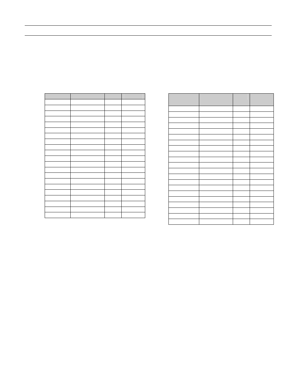
Physical Input Registers-Analog Inputs(AI)
13
Analog Input Registers
Lighting controller contains three on-board Analog
Inputs and upto 16 remote Inputs ( 8 per Daylight
Optimisation module . The present value of the Analog
Input objects are mapped as indicated in table 19.
Analog Input (AI) Value- (Registers 101-148)
Register
AI Input
Type
Format
101 – 102
AI1 On-board
R
Float
103 – 104
AI2 On-board
R
Float
105 – 106
AI3 On-board
R
Float
117 – 118
AI-601
R
Float
119 – 120
AI-602
R
Float
121 – 122
AI-603
R
Float
123 – 124
AI-604
R
Float
125 – 126
AI-605
R
Float
127 – 128
AI-606
R
Float
129 – 130
AI-607
R
Float
131 – 132
AI-608
R
Float
133 – 134
AI-701
R
Float
135 – 136
AI-702
R
Float
137 – 138
AI-703
R
Float
139 – 140
AI-704
R
Float
141 – 142
AI-705
R
Float
143 – 144
AI-706
R
Float
145 – 146
AI-707
R
Float
147 – 148
AI-708
R
Float
Table 19. Analog Input Registers
Analog Input (AI) Object (Registers 1001 – 1272)
Table 20 shows different registers associated with each
AI.
Register
AI Input
Type
Conf
Ref
1001 – 1009
AI1 On-board
RW
1010 – 1018
AI2 On-board
RW
1019 – 1027
AI3 On-board
RW
1101 – 1109
AI-601
RW
AIC1
1110 – 1118
AI-602
RW
AIC1
1119 – 1127
AI-603
RW
AIC1
1128 – 1136
AI-604
RW
AIC1
1137 – 1145
AI-605
RW
AIC1
1146 – 1154
AI-606
RW
AIC1
1155 – 1163
AI-607
RW
AIC1
1164 – 1172
AI-608
RW
AIC1
1201 – 1209
AI-701
RW
AIC1
1210 – 1218
AI-702
RW
AIC1
1219 – 1227
AI-703
RW
AIC1
1228 – 1236
AI-704
RW
AIC1
1237 – 1245
AI-705
RW
AIC1
1246 – 1254
AI-706
RW
AIC1
1255 – 1263
AI-707
RW
AIC1
1264 – 1272
AI-708
RW
AIC1
Table 20. Analog Input Property Registers
Analog Input (AI) Properties:
Each AI object exposes the following properties via
Function codes 3/6/16. There are 6 properties
available: Value, Calibration and Configuration Ref
properties take multiple registers and Value &
Reliability can only be written if OutOfService is True
(OutofService means breaker is in manual mode). To
remove a Configuration Ref, write 0 into the
corresponding registers for object type and instance.
Table 21 shows different registers of AI1 object.