A series – GE Industrial Solutions A Series Lighting Control Panelboards Modbus Register Map User Manual
Page 10
A Series
®
Lighting Controller Modbus Register Map
Introduction
4
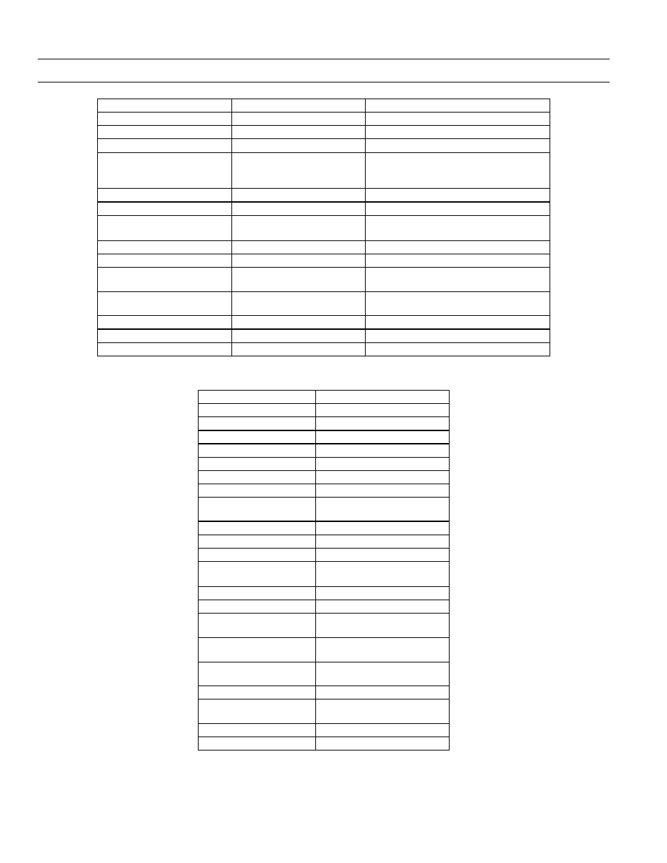
Object
Quantity
Comments
DEV – Device Information
1 per controller
Fixed registers
INPUTS:
MI – Multi-state Input
80 = 16 inputs * 5 Modules
Switch Input Modules.
AI - Analog Input
19 = 3 On-board +
(8 inputs * 2
Modules)
Daylight Optimization Modules.
AV – Analog Variables
16 = 8 inputs * 2 Modules
Daylight Optimization Modules.
OUTPUTS:
BO - Binary Output
66 = Breakers
4 = Special Outputs
BV – Binary Variables
66
1 Light switch per Breaker
Operational Control:
LG - Lighting Group
16
Each controlling up to 33 local
outputs.
SCH – Schedule
16
7 Day schedules - with 16 On/Off times
per day (+ 2 Calendar references)
CAL – Calendar
2
90 Date entries spanning 10 years
CEL - Compact Event Log
1 per controller
1500 timestamp event records
LS – Load Shed
1
66 outputs, 5 shed levels
Table 3. Object types supported by the Lighting Controller.
Object Type
Object ID for MODBUS
AI - Analog Input
0
AO - Analog Output
1
AV - Analog Variable
2
BI - Binary Input
3
BO - Binary Output
4
BV - Binary Variable
5
CAL – Calendar
6
DEV – Device
Information Object
8
CO – Control Loop
12
MI – Multi-state Input
13
MO – Multi-state Output
14
MV – Multi-state Value
19
SCH – Schedule
17
TL - Trend Log
20
AIC - Analog Input
Configuration
176
BDC - Binary Device
Configuration
178
MIC – Multi-state Input
Configuration
183
LS – Load Shed
182
CEL – Compact Event
Log
297
LNK – LINKnet Device
299
LG - Lighting Group
303
Table 4. Object ID