Serial bus communications, Digital feature descriptions, Car2912te series front-end – GE Industrial Solutions CAR2912TE series User Manual
Page 8: Preliminary data sheet
GE
Preliminary Data Sheet
CAR2912TE series front-end
Input: 90Vac to 264Vac; Output: 12Vdc @ 2900W; 3.3 or 5Vdc @ 4A Standby
October 21, 2013
©2013 General Electric Company. All rights reserved.
Page 8
restart if internal temperatures recover within normal
operational levels. At that time the signal reverts back to its
open collector (HI) state.
Fault:
This signal goes LO for any failure that requires rectifier
replacement. These faults may be due to:
•
Fan failure
•
Over-temperature warning
•
Over-temperature shutdown
•
Over-voltage shutdown
•
Internal Rectifier Fault
PS Present:
This signal notifies the system controller that a
power supply is physically present in the slot. This signal pin is
pulled down to Output_return by the power supply.
Serial Bus Communications
The I²C interface facilitates the monitoring and control of
various operating parameters within the unit and transmits
these on demand over an industry standard I²C Serial bus.
All signals are referenced to ‘Output Return’.
Pull-up resistors:
The
clock, data, and SMBusAlert# lines do
not have any internal pull-up resistors inside the power
supply. The customer is responsible for ensuring that the
transmission impedance of the communications lines
complies with I
2
C and SMBus standards.
Serial Clock (SCL):
The clock pulses on this line are generated
by the host that initiates communications across the I²C
Serial bus. This signal needs to be pulled HI externally through
a resistor as necessary to ensure that rise and fall time timing
and the maximum sink current is in compliance to the I²C
/SMBus specifications.
Serial Data (SDA):
This line is a bi-directional data line. This
signal needs to be pulled HI externally through a resistor as
necessary to ensure that rise and fall time timing and the
maximum sink current is in compliance to the I²C /SMBus
specifications.
SMBUSAlert#:
This hardware signal pin is normally HI. When
asserted (logic LO) it signifies to the system controller that the
state of the power supply has changed or that
communication errors occurred.
Digital Feature Descriptions
PMBus™ compliance:
The power supply is compliant to the
Power Management Bus (PMBus™) rev1.2 requirements with
the exception of response to the Alert Response Address (ARA)
command. This is further explained under the section on ARA.
The power supply clears the STATUS and ALARM registers and
the SMBAlert# signal after a successful read back of the
information in these registers, with the exception of
communications error alarms (PEC error, data error,
command error). If the alarm state is still present the status
and alarm registers get reset into their alarm state, however,
the SMBAlert# does not assert again.
‘Manufacturer Specific’ commands are used to support
instructions that are not offered by the PMBus™ specification.
All communication over the PMBus interface must support
Packet Error Checking (PEC). The PMBus master must
generate the correct PEC byte for all transactions, and check
the PEC byte returned by the power supply.
Non-volatile memory is used to store configuration settings.
Not all settings programmed into the device are
automatically saved into this non-volatile memory. Only those
specifically identified as capable of being stored can be
saved. (see the Table of Commands for which command
parameters can be saved to non-volatile storage).
Non-supported commands:
Non supported commands are
flagged by setting the appropriate STATUS bit and issuing an
SMBAlert# to the ‘host’ controller. If a non-supported read is
requested the power supply will return 0x00h for data.
Data out-of-range:
The power supply validates data settings
and sets the data out-of-range bit and SMBAlert# if the data
is not within acceptable range.
Master/Slave:
The ‘host controller’ is always the MASTER.
Power supplies are always SLAVES. SLAVES cannot initiate
communications or toggle the Clock. SLAVES also must
respond expeditiously at the command of the MASTER as
required by the clock pulses generated by the MASTER.
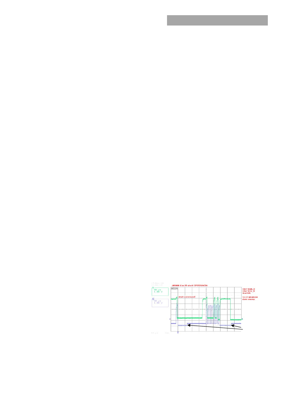
Clock stretching:
The ‘slave’ µController inside the power
supply may initiate clock stretching if it is busy and it desires
to delay the initiation of any further communications. During
the clock stretch the ‘slave’ may keep the clock LO until it is
ready to receive further instructions from the host controller.
The maximum clock stretch interval is 25ms.
The host controller needs to recognize this clock stretching,
and refrain from issuing the next clock signal, until the clock
line is released, or it needs to delay the next clock pulse
beyond the clock stretch interval of the power supply.
Figure 1. Example waveforms showing clock stretching.
Note that clock stretching can only be performed after
completion of transmission of the 9
th
ACK bit, the exception
being the START command.
Clock
Stretch