General performance descriptions, Car2912te series front-end, Preliminary data sheet – GE Industrial Solutions CAR2912TE series User Manual
Page 18: Dual master control
GE
Preliminary Data Sheet
CAR2912TE series front-end
Input: 90Vac to 264Vac; Output: 12Vdc @ 2900W; 3.3 or 5Vdc @ 4A Standby
October 21, 2013
©2013 General Electric Company. All rights reserved.
Page 18
LEDS test ON: Will turn-ON simultaneously the front panel
LEDs of the Power supply sequentially 7 seconds ON and 2
seconds OFF until instructed to turn OFF. The intent of this
function is to provide visual identification of the power supply
being talked to and also to visually verify that the LEDs
operate and driven properly by the micro controller
.
LEDS test OFF: Will turn-OFF simultaneously the four front
panel LEDs of the Power supply.
OR’ing Test: This command verifies functioning of output
OR’ing. At least two paralleled power supplies are required.
The host should verify that N+1 redundancy is established. If
N+1 redundancy is not established the test can fail. Only one
power supply should be tested at a time.
Verifying test completion should be delayed for
approximately 30 seconds to allow the power supply
sufficient time to properly execute the test.
Failure of the isolation test is not considered a power supply
FAULT because the N+1 redundancy requirement cannot be
verified. The user must determine whether a true isolation
fault indeed exists.
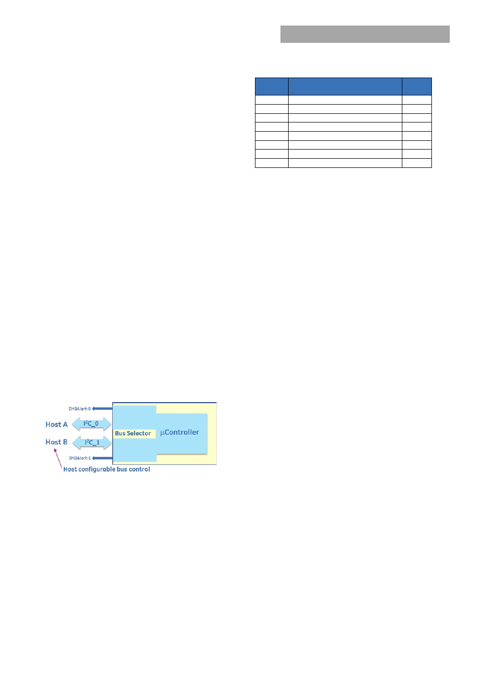
Dual Master Control :
Two independent I
2
C lines and SMBAlert signals provide true
communications redundancy allowing two independent
controllers to sequentially control the power supply.
A short or an open connection in one of the I
2
C lines does not
affect communications capability on the other I
2
C line. Failure
of a ‘master’ controller does not affect the power supplies
and the second ‘master’ can take over control at any time
when the bus is idle.
Conceptual representation of the dual I
2
C bus system.
The SMBAlert line exciting the power supply combines the
Alert functions of power supply control and
dual_bus_control.
Read Bus Status(0xD9):
Bus_Status is a single byte read
back. The command can be executed by either master at
any time independent of who has control.
The µC may issue a clock stretch, as it can for any other
instruction, if it requires a delay because it is busy with
other activities.
Automatically resetting into the default state requires the
removal of bias supply from the processors.
Bit
Position
Flag
Default
Value
7
Bus 1 command error
0
6
Bus 1 SMBAlert enabled
0
5
Bus 1 requested control
0
4
Bus 1 has control of the PS
0
3
Bus 0 command error
0
2
Bus 0 SMBAlert enabled
0
1
Bus 0 requested control
0
0
Bus 0 has control of the PS
1
Command Execution:
The master not in control can issue
two commands on the bus, take_over_bus_control and
clear_faults
Take over Bus Control(0xDA):
This command instructs the
internal µC to switch command control over to the ‘master’
that initiated the request.
Actual transfer is controlled by the I
2
C selector portion of the
µC. A bus transfer only occurs during an idle state when the
‘master’ currently in control (in the execution process of a
control command) has released the bus by issuing a STOP
command. Control can be transferred at any time if the
‘master’ being released is executing a read instruction that
does not affect the transfer of command control. Note; The
µC can handle read instructions from both busses
simultaneously.
The command follows PMBus™ standards and it is not
executed until the trailing PEC is validated.
Status Notifications:
Once control is transferred both
SMBAlert lines should get asserted by the I2C selector section
of the µC. The released ‘master’ is notified that a STATUS
change occurred and he is no longer in control. The
connected ‘master’ is notified that he is in control and he can
issue commands to the power supply. Each master must
issue a clear_faults command to clear his SMBAlert signal.
If the SMBAlert signal was actually triggered by the power
supply and not the I
2
C selector selector section of the µC,
then only the ‘master’ in control can clear the power supply
registers.
Incomplete transmissions should not occur on either bus.
General performance descriptions
Default state:
Power supplies are programmed in the default
state to automatically restart after a shutdown has occurred.
The default state can be reconfigured by changing non-
volatile memory (Store_default_code).
Delayed overcurrent shutdown during startup:
Power
supplies are programmed to stay in a constant current state
for up to 20 seconds during power up. This delay has been
introduced to permit the orderly application of input power to