Pmbustm commands, Car2912te series front-end, Preliminary data sheet – GE Industrial Solutions CAR2912TE series User Manual
Page 10: Pmbus, Commands
GE
Preliminary Data Sheet
CAR2912TE series front-end
Input: 90Vac to 264Vac; Output: 12Vdc @ 2900W; 3.3 or 5Vdc @ 4A Standby
October 21, 2013
©2013 General Electric Company. All rights reserved.
Page 10
Alert Response Address (ARA):
This feature enables the
‘master’ to rapidly determine which ‘slave’ power supply
triggered the SMBAlert signal without having to poll each
power supply one at a time. During normal operation the
power supply activates (pulls down LO) the Alert signal line
indicating that it needs attention when a ‘state’ change
occurs. The master can determine who pulled the ‘alert’ line
by sending out the alert-response-address, address 12b, with
a ‘read’ instruction. If the power supply triggered the ‘alert’ it
should respond back with its address. The instruction takes
the form below;
1
8
1
8
1
8
1
1
S
ARA address
Rd A My address
A
PEC
A
P
If during the ARA response multiple power supplies send out
their addresses, then the actual address received by the
master is the lowest address from the combinations of those
power supplies that responded.
The ‘my address’ field contains the address of the power
supply in the 7 most significant bits (msb) of the byte. The lsb
of the byte is a don’t care, it could be a 0 or a 1. For more
information refer to the SMBus specification.
The µC does not have the ability to listen to the actual
address that is sent over the bus, if multiple ‘slaves’ respond
simultaneously, and therefore it does not clear its SMBAlert
line. The host should read the status of the power supply
whose address was actually sent across the bus. Reading
either the read_status [0 x D0] or status_word [0 x 79] would
clear the SMBALert line of the power supply that was
addressed. The power supply will not re-assert the SMBAlert
line unless the status states actually changed.
If the SMBAlert line is still asserted, the host should send out
an ARA request again and find out who else asserted
SMBAlert. This process needs to continue until the SMBAlert is
released which is a clear indication that all power supplies
that asserted SMBAlert have had their status states read
back.
Dual, redundant buses:
Two independent I
2
C lines provide
true communications bus redundancy and allow two
independent controllers to sequentially control the power
supply. For example, a short or an open connection in one of
the I
2
C lines does not affect communications capability on the
other I
2
C line. Failure of a ‘master’ controller does not affect
the power supplies and the second ‘master’ can take over
control at any time.
Conceptually a Digital Signal Processor (DSP) referenced to
Vout(-) of the power supply provides secondary control. A
Bidirectional Isolator provides the required isolation between
power GRD, Vout(-) and signal GRD (Logic_GRD). A secondary
micro controller provides instructions to and receives
operational data from the DSP. The secondary micro
controller also controls the communications over two
independent I2C lines to two independent system controllers.
The secondary micro controller is designed to default to I2C_0
when powered up. If only a single system controller is utilized,
it should be connected to I2C_0. In this case the I2C_1 line is
totally transparent as if it does not exist.
If two independent system controllers are utilized, then one of
them should be connected to I2C_0 and the other to I2C_1.
At power up the master connected to I2C_0 has control of the
bus. See the section on Dual Master Control for further
description of this feature.
PMBus
TM
Commands
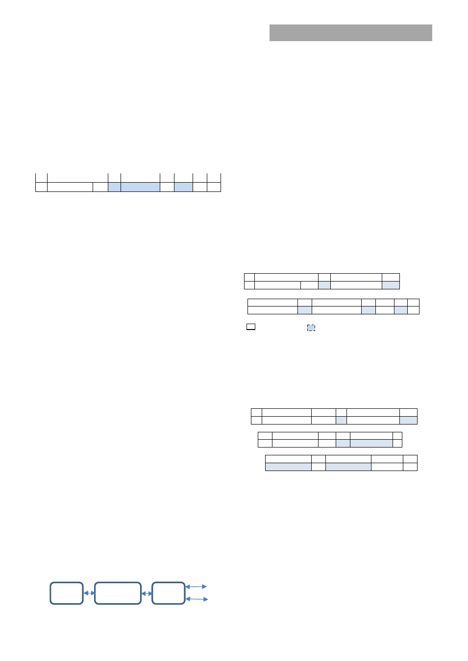
Standard instruction:
Up to two bytes of data may follow an
instruction depending on the required data content. Analog
data is always transmitted as LSB followed by MSB. PEC is
optional and includes the address and data fields.
1
8
1
8
1
S Slave address
Wr A Command Code
A
8
1
8
1
8
1 1
Low data byte
A
High data byte
A
PEC A
P
Master to Slave Slave to Master
SMBUS annotations; S – Start , Wr – Write, Sr – re-Start, Rd
– Read,
A – Acknowledge, NA – not-acknowledged, P – Stop
Standard READ:
Up to two bytes of data may follow a READ
request depending on the required data content. Analog
data is always transmitted as LSB followed by MSB. PEC is
mandatory and includes the address and data fields
.
1
7
1
1
8
1
S
Slave address
Wr
A Command Code
A
1
7
1
1
8
1
Sr Slave Address
Rd
A
LSB
A
8
1
8
1
1
MSB
A
PEC
No-ack
P
Block communications:
When writing or reading more than
two bytes of data at a time BLOCK instructions for WRITE and
READ commands are used instead of the Standard
Instructions above to write or read any number of bytes
greater than two.
µC
DSP
Bidirectional
Isolator
I
2
C_0
I
2
C 1