Status-2, Status-1, Alarm-2 – GE Industrial Solutions CAR2912TE series User Manual
Page 16: Alarm-1, Car2912te series front-end, Preliminary data sheet, Manufacturer-specific pmbus, Commands
GE
Preliminary Data Sheet
CAR2912TE series front-end
Input: 90Vac to 264Vac; Output: 12Vdc @ 2900W; 3.3 or 5Vdc @ 4A Standby
October 21, 2013
©2013 General Electric Company. All rights reserved.
Page 16
Manufacturer-Specific PMBus
TM
Commands
Many of the manufacturer-specific commands read back
more than two bytes
.
If more than two bytes of data are
returned, the standard SMBus
TM
Block read is utilized. In this
process, the Master issues a Write command followed by the
data transfer from the power supply. The first byte of the
Block Read data field sends back in hex format the number of
data bytes, exclusive of the PEC number, that follows. Analog
data is always transmitted LSB followed by MSB. A No-ack
following the PEC byte signifies that the transmission is
complete and is being terminated by the ‘host’.
Mfr_Specific Status and alarm registers:
The content and
partitioning of these registers is significantly different than
the standard register set in the PMBus™ specification. More
information is provided by these registers and they are either
accessed rapidly, at once, using the ‘multi parameter’ read
back scheme of this document, or in batches of two STATUS
and two ALARM registers.
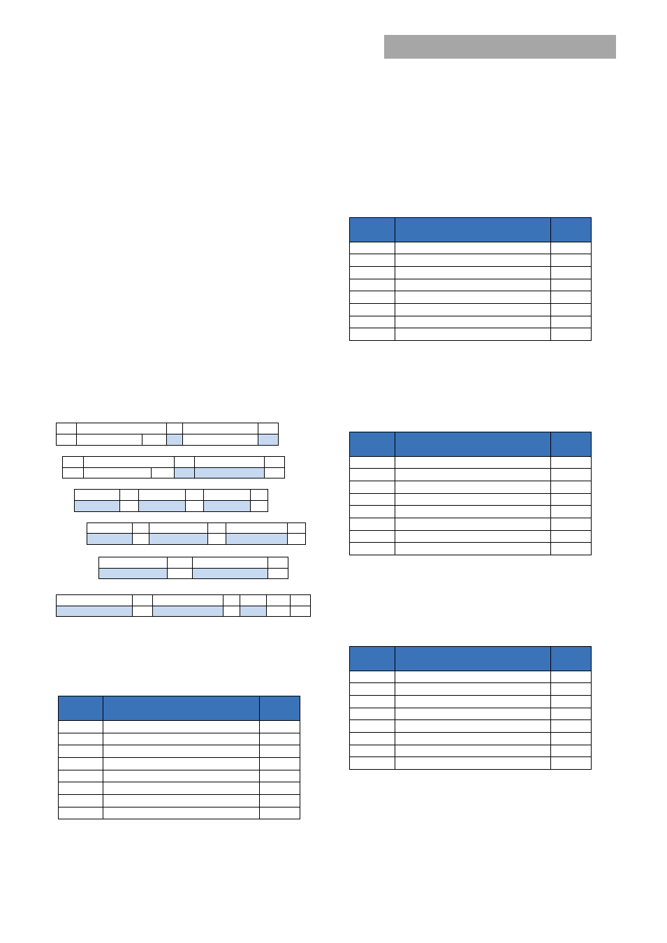
Read_status (D0h) :
This ‘manufacturer specific’ command is
the basic read back returning STATUS and ALARM register
data, output voltage, output current, and internal
temperature data in a single read.
1
8
1
8
1
S
Slave address
Wr A Command Code
A
1
8
1
8
1
Sr
Slave address
Rd
A Byte count = 10
A
8
1
8
1
8
1
Status-2
A
Status-1
A
Alarm-2
A
8
1
8
1
8
1
Alarm-1
A Voltage LSB
A
Voltage MSB
A
8
1
8
1
Current LSB
A
Current MSB
A
8
1
8
1
8
1
1
Temperature LSB
A Temperature MSB A PEC NA
P
Read_Status_state (0xD1):
This command returns the
STATUS-2 and STATUS-1 register values using the standard
‘read’ format.
Status-2
Bit
Position
Flag
Default
Value
7
PEC Error
0
6
Will restart
0
5
Invalid_Instruction
0
4
Power_Capacity [HL = 1]
x
3
Isolation test failed
0
2
Restarted_OK
0
1
Data out_of_range
0
0
Remote ON/OFF [logic HI = 1]
x
Isolation test failed: The ‘system controller’ has to determine
that sufficient capacity exists in the system to take a power
supply ‘off line’ in order to test its isolation capability. Since
the power supply cannot determine whether sufficient
redundancy is available, the results of this test are provided,
but the ‘internal fault’ flag is not set.
Status-1
Bit
Position
Flag
Default
Value
7
X
0
6
Isolation_Test_OK
0
5
Internal_Fault
0
4
Shutdown
0
3
Service LED ON
0
2
External_Fault
0
1
LEDs_Test_ON
0
0
Output ON
x
Read_Alarm_state (0xD2):
This command returns the
ALARM-2 and ALARM-1 register values using the standard
‘read’ format.
Alarm-2
Bit
Position
Flag
Default
Value
7
FAN_Fault
0
6
No_Primary
0
5
Primary_OT
0
4
DC/DC_OT
0
3
Vo lower than BUS
0
2
Thermal sensor filed
0
1
Stby_out_of_limits
0
0
Power_Delivery
0
Power Delivery: The power supply compares its internal
sourced current to the current requested by the current share
pin. If the difference is > 10A, a fault is issued.
Alarm-1
Bit
Position
Flag
Default
Value
7
POWER LIMIT
0
6
PRIMARY Fault
0
5
OT_Shutdown
0
4
OT_Warning
0
3
IN OVERCURRENT
0
2
OV_Shutdown
0
1
VOUT_out_of_limits
0
0
VIN_out_of_limits
0