Car2912te series front-end, Preliminary data sheet – GE Industrial Solutions CAR2912TE series User Manual
Page 21
GE
Preliminary Data Sheet
CAR2912TE series front-end
Input: 90Vac to 264Vac; Output: 12Vdc @ 2900W; 3.3 or 5Vdc @ 4A Standby
October 21, 2013
©2013 General Electric Company. All rights reserved.
Page 21
Re-program Status indication:
The FAULT LED is utilized for
indicating the status of the re-programming process.
Status
State
Description
Idle
Blink
Not communicating
In boot block
Wink
Application is good
Upgrading
Fast blink
Application is erased or
programming in progress
Fault
ON
Erase or re-program failed
Blink: 0.5 seconds ON, 0.5 seconds OFF
Wink: 0.25 seconds ON, 0.75 seconds OFF
Fast Blink: 0.25 seconds ON. 0.25 seconds OFF
Product identifier:
Compatibility determination between the
front-end and the upgrade code
•
Compatibility code (0 x E0) – Describes the product’s
hardware revision
•
Model (0 x 9A)
•
Series (0 x 9B)
•
Firmware rev (0 x DD)
Compatibility Code:
A unique ASCII character set of up to 16
characters defining the hardware configuration.
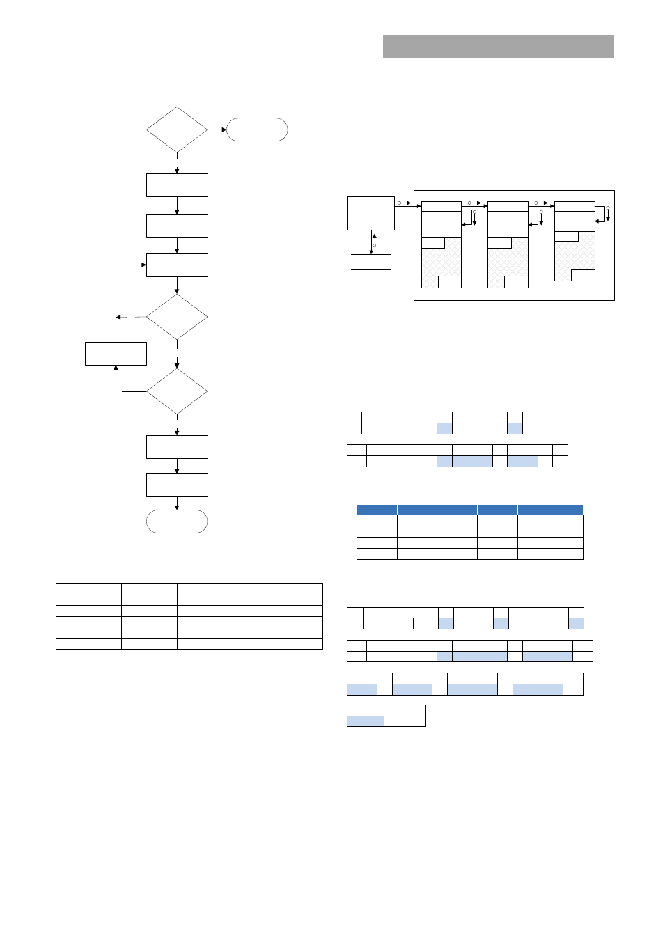
Level_x: Device to be re-programmed:
The three µC’s are
interconnected within the module. The System Controller
always talks through the I2C interface. The I2C interface
transfers information to both the DC-DC and PFC µC’s
through the DC-DC µC. The level structure identifies where the
final destination resides.
System
Controller
program file
available
application
code space
application
checksum
address
checksum
boot loader
available
application
code space
application
checksum
address
checksum
boot loader
available
application
code space
application
checksum
address
checksum
boot loader
I2C Interface
DC-DC
PFC
•
Level 1 – PFC µC
•
Level 2 – DC/DC µC
•
Level 3 – I2c µC
Application status (0 x E0):
Boot Loader’s present status
1
8
1
8
1
S Slave addr Wr
A Cmd – 0xE0 A
1
8
1
8
1
8
1 1
Sr Slave addr Rd
A Status
A chsum NA P
Status bits:
Up nibble
Event
Lo nibble
Event
0 x 0001 Application erased
0 x 0001
0 x 0002 Checksum invalid
0 x 0002
0 x 0004 Sequence order NG 0 x 0004 Busy
0 x 0008 Address out of range 0 x 0008 In boot loader
Memory capability (0 x E1):
Provides information about the
capability of the micro controller
1
8
1
8
1
8
1
S Slave addr Wr
A Level-x A Cmd – 0xE1
A
1
8
1
8
1
8
1
Sr Slave addr Rd
A Byte count=5 A Max bytes A
8
1
8
1
8
1
8
1
ET-LSB A ET-MSB A Buffer-LSB A Buffer-MSB A
8
1
1
chsum NA
P
Max bytes: Device capability in a single data packet
ET: Erase time for the entire applications space in ms
Buffer: time required to program buffer of code in µs
Boot loader (0 x E2):
A sector in device memory that controls
the start of the application. This sector is also instrumental in
managing the upgrade process starting with erasing the
send enter boot
block command
read memory info
and erase memory
send done
command
is
sequence
correct?
no
sequence++
yes
done?
yes
send data packet
no
send exit boot
block command
Done
Is program file
compatible?
yes
no
Done
no