Car2912te series front-end, Preliminary data sheet – GE Industrial Solutions CAR2912TE series User Manual
Page 17
GE
Preliminary Data Sheet
CAR2912TE series front-end
Input: 90Vac to 264Vac; Output: 12Vdc @ 2900W; 3.3 or 5Vdc @ 4A Standby
October 21, 2013
©2013 General Electric Company. All rights reserved.
Page 17
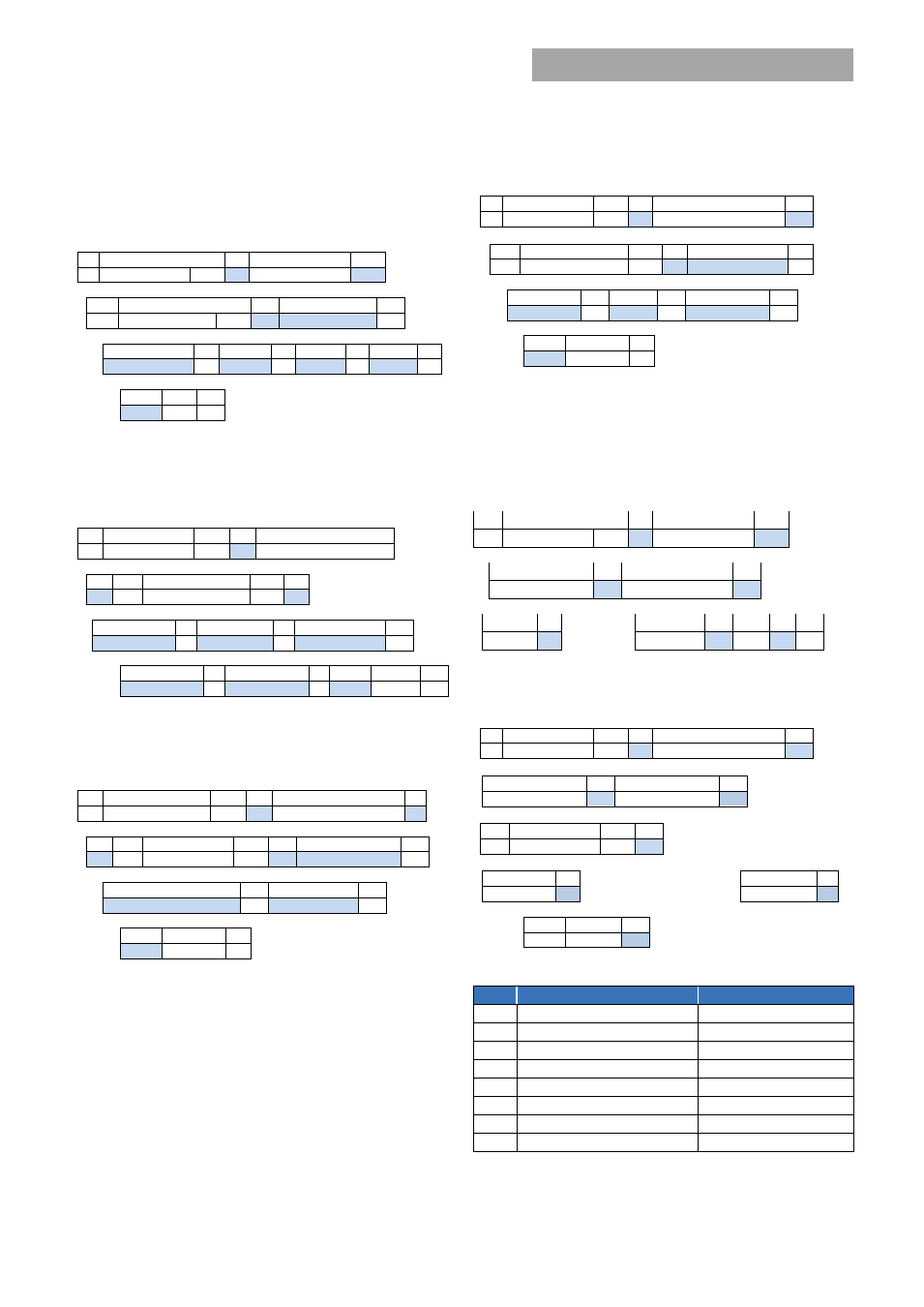
Read_Fan_speed (0 x D3) :
Returns the commanded speed in
percent and the measured speed in RPM. Up to 3 fans are
supported. If a fan does not exist, or if the command is not
supported the unit return 0x00.
1
8
1
8
1
S Slave address
Wr A Command 0xE1
A
1
8
1
8
1
Sr
Slave address
Rd
A
Byte count = 4
A
8
1
8
1
8
1
8
1
Adjustment % A Fan-1
A Fan-2
A Fan-3 A
8
1
1
PEC
NA
P
Read input string (0xD4):
Reads back the input voltage and
input power consumed by the power supply. In order to
improve the resolution of the input voltage reading the data is
shifted by 75V.
1
7
1
1
8
S
Slave address
Wr
A
Command Code 0xDC
1
1
7
1
1
A
Sr
Slave Address
Rd
A
8
1
8
1
8
1
Byte Count = 4 A Voltage - LSB A Voltage - MSB
A
8
1
8
1
8
1
1
Power - LSB
A Power - MSB A PEC No-ack P
Read_firmware_rev [0 x D5]:
Reads back the firmware
revision of the two µC in the power supply.
1
7
1
1
8
1
S
Slave address
Wr
A Command Code 0xDD A
1
1
7
1
1
8
1
A
Sr
Slave Address
Rd
A
Byte Count = 2
A
8
1
8
1
Primary micro revision
A
DSP revision
A
8
1
1
PEC
NA
P
For example; the read returns one byte for each device (i.e. 0
x 002114h ). The sequence is primary micro, DSP, and I
2
C
micro. 0x00 in the first byte indicates that revision information
for the primary micro is not supported. The number 21 for the
DSP indicates revision
2.1, and the number 14 for the i2c
micro indicates revision 1.4.
Read_run_timer [0 x D6]:
This command reads back the
recorded operational ON state of the power supply in hours.
The operational ON state is accumulated from the time the
power supply is initially programmed at the factory. The
power supply is in the operational ON state both when in
standby and when it delivers main output power. Recorded
capacity is approximately 10 years of operational state.
1
7
1
1
8
1
S Slave address
Wr
A Command Code 0xDE
A
1
7
1
1
8
1
Sr
Slave Address
Rd
A
Byte count = 3
A
8
1
8
1
8
1
Time - LSB
A
Time
A
Time - MSB
A
8
1
1
PEC
No-ack
P
EEPROM record (0xD9):
The µC contains 128 bytes of
reserved EEPROM space for customer use, such as a
customized set of FRU_ID parameters.
To write into the EEPROM section, after the command code,
the starting memory location must be entered followed by a
block write, and terminated by the PEC number;
1
8
1
8
1
S
Slave address
Wr A Command 0xD9
A
8
1
8
1
Memory location A
Byte count ≤ 32
A
8
1
8
1
8
1
1
Byte 1
A ………………….. Byte ≤ 32
A
PEC A
P
The highest memory location is address 128b.
To read contents from the EEPROM section
1
7
1
1
8
1
S Slave address
Wr
A Command 0xD9
A
8
1
8
1
Memory location A
Byte count ≤ 32
A
1
7
1
1
Sr
Slave address
Rd
A
8
1
8
1
Byte 1
A ………………………………………………….
Byte ≤ 32
A
8
1
1
PEC
No-ack P
Test Function (0xDF)
Bit
Function
State
0
LED test
1=ON, 0=OFF
1
reserved
2
reserved
3
reserved
4
Or’ing test
1=ON, 0=OFF
5
reserved
6
reserved
7
reserved