Car2912te series front-end, Preliminary data sheet, Command descriptions – GE Industrial Solutions CAR2912TE series User Manual
Page 12
GE
Preliminary Data Sheet
CAR2912TE series front-end
Input: 90Vac to 264Vac; Output: 12Vdc @ 2900W; 3.3 or 5Vdc @ 4A Standby
October 21, 2013
©2013 General Electric Company. All rights reserved.
Page 12
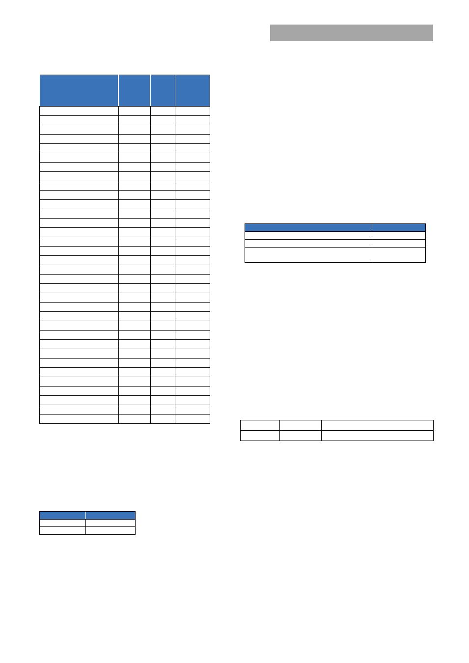
Command
Hex
Code
Data
Field
Non-
Volatile
Memory
Storage
Read_Vout
0x8B
2
Read_Iout
0x8C
2
Read_temperature_1
0x8D
2
Read_temperature_2
0x8E
2
Read_temperature_3
0x8F
2
Read_fan_speed_1
0x90
2
Read_fan_speed_2
0x91
2
Read_Pin
0x97
2
Mfr_ID
0x99
5
Mfr_model
0x9A
16
Mfr_revision
0x9B
4
Mfr_serial
0x9E
15
Read_status
0xD0
10
Read_Status_state
0xD1
2
Read_Alarm_state
0xD2
2
Read_fan_speed
0XD3
4
Read_input_string
0xD4
2
Read_firmware_rev
0xD5
3
Read_run_timer
0xD6
3
Read Bus Status
0xD7
1
Take over bus control
0xD8
EEPROM Record
0xD9
128
Stretch_LO_25ms
0XDA
0
Test Function
0xDF
1
Compatibility code
0xE0
20
Memory capability
0xE1
5
Boot loader
0xE2
1
Data transfer
0xE3
≤32
Command Descriptions
Operation (0x01) :
By default the Power supply is turned ON
at power up as long as Power ON/OFF signal pin is active HI.
The Operation command is used to turn the Power Supply ON
or OFF via the PMBus. The data byte below follows the
OPERATION command.
FUNCTION
DATA BYTE
Unit ON
80
Unit OFF
00
To RESET the power supply cycle the power supply OFF, wait
at least 2 seconds, and then turn back ON. All alarms and
shutdowns are cleared during a restart.
Clear_faults (0x03):
This command clears all STATUS and
FAULT registers and resets the SMBAlert# line of both the
power supply and I
2
C bus STATUS register.
If a fault, or a STATUS needing attention, still persists after the
issuance of the clear_faults command, the specific registers
indicating the fault are reset and the specific SMBAlert# line is
activated again.
WRITE_PROTECT register (0x10):
Used to control writing to
the PMBus device. The intent of this command is to provide
protection against accidental changes. All supported
command parameters may have their parameters read,
regardless of the write_protect settings. The contents of this
register can be stored to non-volatile memory using the
Store_default_code command. The default setting of this
register is disable_all_writes except write_protect 0x80h.
FUNCTION
DATA BYTE
Enable all writes
00
Disable all writes except write_protect
80
Disable all writes except write_protect and
OPERATION
40
Restore_Default_All (0x12):
Restores all register values and
responses to the default parameters set in the power supply.
Store_default_code (0x13):
Changes the default setting of a
single register. In this fashion some protection is offered to
ensure that only those registers that are desired to be
changed are in fact changed.
Restore_default_code (0x14):
Restore only a specific register
parameter to its default parameter.
Vout_mode (0x20):
This is a ‘read only’ register. The upper
three bits specify the supported data format, in this case
Direct mode. The lower five bits are not used when direct
mode is specified since there are three variables for each
conversion.
Mode
Bits [7:5]
Bits [4:0] (Parameter)
Direct
010b
Set to 00000b
Vout_Command (0x21) :
This command is used to change the
output voltage of the power supply.
Changing the output voltage should be performed
simultaneously to all power supplies operating in parallel
using the Global Address (Broadcast) feature. If only a single
power supply is instructed to change its output, it may
attempt to source all the required power which can cause
either a power limit or shutdown condition.
Software programming of output voltage permanently
overrides the set point voltage configured by the Vprog signal
pin. The program no longer looks at the ‘Vprog pin’ and will
not respond to any hardware voltage settings. If power is
removed from the µController it will reset itself into its default