10 additional connections, Af-650 gp high power operating instructions – GE Industrial Solutions AF-650 GP General Purpose Drive (460_575_690V 125HP and above) User Manual
Page 71
3.10 Additional Connections
3.10.1 Mechanical Brake Control
In hoisting/lowering applications, it is necessary to be able to control an electro-mechanical brake:
•
Control the brake using any relay output or digital output (terminal 27 or 29).
•
Keep the output closed (voltage-free) as long as the frequency converter is unable to ‘support’ the motor, for example due to the load being too heavy.
•
Select Mechanical brake control [32] in E-2# for applications with an electro-mechanical brake.
•
The brake is released when the motor current exceeds the preset value in par. B-20 Release Brake Current.
•
The brake is engaged when the output frequency is less than the frequency set in par. B-21 Activate Brake Speed [RPM]or par. B-22 Activate Brake Speed
[Hz], and only if the frequency converter carries out a stop command.
If the frequency converter is in alarm mode or in an over-voltage situation, the mechanical brake immediately cuts in.
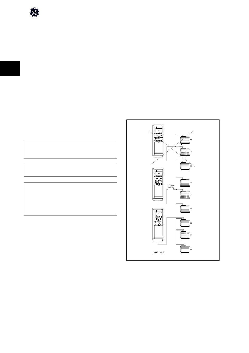
3.10.2 Parallel Connection of Motors
The frequency converter can control several parallel-connected motors. The
total current consumption of the motors must not exceed the rated output
current I
M,N
for the frequency converter.
NB!
Installations with cables connected in a common joint as in the illustration
below, is only recommended for short cable lengths.
NB!
When motors are connected in parallel, par. P-04 Auto Tune cannot be used.
NB!
The electronic thermal overload of the frequency converter cannot be used
as motor protection for the individual motor in systems with parallel-con-
nected motors. Provide further motor protection by e.g. thermistors in each
motor or individual thermal relays (circuit breakers are not suitable as pro-
tection).
Problems may arise at start and at low RPM values if motor sizes are widely different because small motors' relatively high ohmic resistance in the stator calls for
a higher voltage at start and at low RPM values.
3.10.3 Motor Thermal Protection
The electronic thermal overload in the frequency converter has received UL-approval for single motor protection, when par. F-10 Electronic Overloadis set for
Elec. OL Trip and par. P-03 Motor Current is set to the rated motor current (see motor name plate).
AF-650 GP High Power Operating Instructions
70
3