Af-650 gp high power operating instructions – GE Industrial Solutions AF-650 GP General Purpose Drive (460_575_690V 125HP and above) User Manual
Page 105
Safe stop Terminal 37
3)
(Terminal 37 is fixed PNP logic):
Voltage level
0 - 24 V DC
Voltage level, logic'0' PNP
< 4 V DC
Voltage level, logic'1' PNP
>20 V DC
Nominal input current at 24 V
50 mA rms
Nominal input current at 20 V
60 mA rms
Input capacitance
400 nF
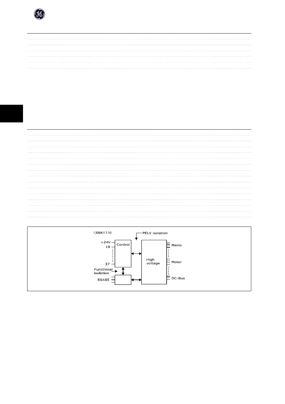
All digital inputs are galvanically isolated from the supply voltage (PELV) and other high-voltage terminals.
1) Terminals 27 and 29 can also be programmed as output.
2) Except safe stop input Terminal 37.
3) Terminal 37 can only be used as safe stop input. Terminal 37 is suitable for category 3 installations according to EN 954-1 (safe stop according to category 0 EN
60204-1) as required by the EU Machinery Directive 98/37/EC. Terminal 37 and the Safe Stop function are designed in conformance with EN 60204-1, EN 50178,
EN 61800-2, EN 61800-3, and EN 954-1. For correct and safe use of the Safe Stop function follow the related information and instructions in the AF-650 GP Design
Guide.
Analog inputs:
Number of analog inputs
2
Terminal number
53, 54
Modes
Voltage or current
Mode select
Switch S201 and switch S202
Voltage mode
Switch S201/switch S202 = OFF (U)
Voltage level
-10 to +10 V (scaleable)
Input resistance, R
i
approx. 10 kΩ
Max. voltage
± 20 V
Current mode
Switch S201/switch S202 = ON (I)
Current level
0/4 to 20 mA (scaleable)
Input resistance, R
i
approx. 200 Ω
Max. current
30 mA
Resolution for analog inputs
10 bit (+ sign)
Accuracy of analog inputs
Max. error 0.5% of full scale
Bandwidth
100 Hz
The analog inputs are galvanically isolated from the supply voltage (PELV) and other high-voltage terminals.
AF-650 GP High Power Operating Instructions
104
5