Firewire bandwidth, Bandwidth guage, For details – Universal Audio UAD POWERED PLUG-INS ver.6.1 User Manual
Page 141: Bus. see, For additional information, For the recommended configuration when
UAD Powered Plug-Ins Manual
- 141 -
Chapter 11: UAD-2 Satellite
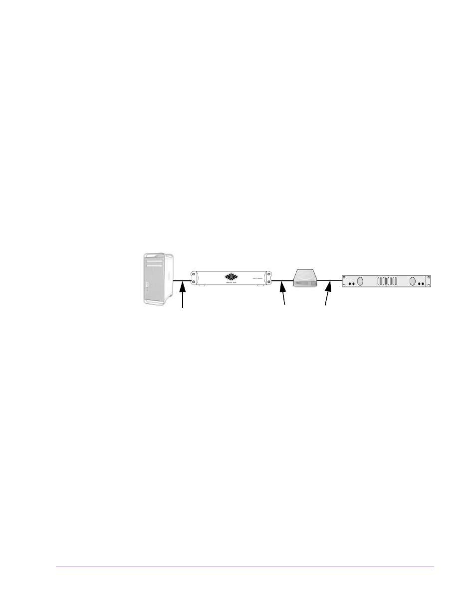
It is possible to configure a FireWire bus to run at both FW400 and FW800
speeds simultaneously if the host computer bus is FW800, supporting maxi-
mum throughput for a mix of FW400+FW800 devices. This is accomplished
by putting any/all FW400 devices AFTER any/all FW800 devices in a daisy
chain (see
Daisy-chain FireWire 400 devices AFTER the FireWire 800 devices in a FW800 bus
If (and only if) FireWire 400 devices are attached to a FireWire 800 bus after
the end of all FireWire 800 devices in a daisy-chain (
800 devices will operate at 800 megabits while the FireWire 400 device op-
erates at 400 megabits.
Important:
This is the recommended configuration when UAD-2 Satellite is
sharing a FireWire 800 bus with FireWire 400 devices.
FireWire Bandwidth
All devices on a FireWire bus must share the available data bandwidth of the
bus, including hard drives and audio interfaces as well as UAD-2 Satellite. If
there is not enough FireWire bandwidth to handle all the data traffic on the
bus, performance issues (such as audio clicks/pops/dropouts or UAD over-
loads) could occur.
Bandwidth
Guage
When UAD-2 Satellite is connected, the UAD Meter window displays the
FireWire Bandwidth gauge (
), showing the amount of
FireWire bandwidth being used by UAD-2 Satellite and other FireWire de-
vices on the bus.
details all of the elements in the
gauge.
Figure 39. FireWire 800 bus – devices running at 800 and 400 megabits (recommended setup)
FW800 Computer
FW400 Audio Interface
FW400 HD
FW800 UAD-2 Satellite
This FireWire bus runs at both 800 and 400 because the FW400
FW bus@800
FW bus@400
devices are located AFTER the FW800 device in the daisy chain.