Getting started, Panel layout – SENA STS Series User Manual
Page 13
13
2. Getting Started
This chapter describes how to set up and configure the STS Series.
- 2.1. Panel Layout explains the layout of the panel and LED indicators.
- 2.2. Connecting The Hardware describes how to connect the power, the network, and the
equipment to the STS Series and how to access the console port using a serial console or a
Telnet from remote location.
- 2.3. Accessing The Web Browser Management Interface describes how to access Web menu
from remote location.
The following items are required to get started.
- One power cable (included in the package)
- Console and Ethernet cables (included in the package)
- Cable kit (included in the package)
- One PC with Network Interface Card (hereafter, NIC) and/or one RS232 serial port.
2.1. Panel Layout
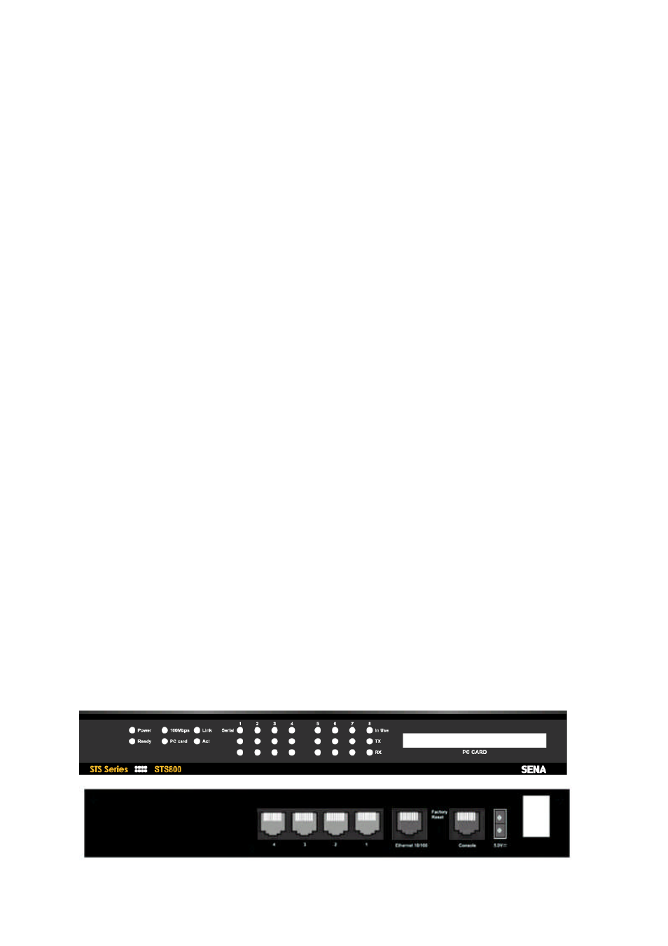
2.1.1. STS400/800 Panel Layout
The STS400/800 has three groups of LED indicator lamps to display the status, as shown in Figure
2-1 and Figure 2-2 (i.e. System, Ethernet and Serial ports). The first three lamps on the left side
indicate Power, Ready and PC Card interface. The next three lamps are for Ethernet 100Mbps, Link
and Act. Next lamps indicate InUse, Receive and Transmit of the serial ports.
Table 2-1 describes the function of each LED indicator lamp. The rear panel shows the serial ports
with RJ45 connector, Ethernet port, the STS400/800 console port and the power socket.