Figure 3-3, Figure 3-4 – B&B Electronics PCI-1711 - Manual User Manual
Page 35
Chapter 3
– 27 –
PCI-1710 series User’s Manual
Advantech Co., Ltd.
www.advantech.com
If one side of the signal source is connected to a local ground, the
signal source is ground-referenced. Therefore, the ground of the signal
source and the ground of the card will not be exactly of the same
voltage. The difference between the ground voltages forms a common-
mode voltage (V
cm
).
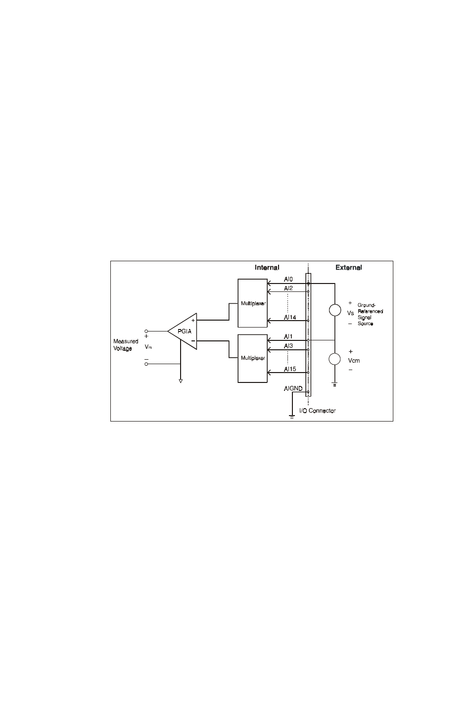
To avoid the ground loop noise effect caused by common-mode
voltages, you can connect the signal ground to the Low input. Figure
3-3 shows a differential channel connection between a ground-
reference signal source and an input channel on the PCI-1710/1710L/
1710HG/1710HGL/1716/1716L. With this connection, the PGIA rejects a
common-mode voltage V
cm
between the signal source and the PCI-
1710/1710L/1710HG/1710HGL/1716/1716L ground, shown as V
cm
in
Figure 3-3.
Figure 3-3: Differential input channel connection - ground reference
signal source
If a floating signal source is connected to the differential input
channel, the signal source might exceed the common-mode signal
range of the PGIA, and the PGIA will be saturated with erroneous
voltage-readings. You must therefore reference the signal source
against the AIGND.
Figure 3-4 shows a differential channel connection between a floating
signal source and an input channel on the PCI-1710/1710L/1710HG/
1710HGL/1716/1716L. In this figure, each side of the floating signal
source is connected through a resistor to the AIGND. This connection
can reject the common-mode voltage between the signal source and
the PCI-1710/1710L/1710HG/1710HGL/1716/1716L ground.