Connecting the mesr9x1-x – B&B Electronics MESR900 Series - Fiber Models - Manual User Manual
Page 16
3. Setup and Connections
VlinxMESR9xx Modbus Gateway
Page 12
Manual Documentation Number MESR9xx-2113m
www.bb-elec.com/
www.bb-europe.com/
When configured for 2-wire operation the connection supports one signal pair: DataB(+)
and DataA(-) signal channels using half-duplex operation. The data lines are differential
with the Data B line positive relative to Data A in the idle (mark) state. Ground provides
a common mode reference.
Connecting the MESR9x1-x
The MESR9x1-x has one serial connection that supports RS-232, RS-422 and RS-485
(2- and 4-wire). The unit has two connectors: a DB-9M connector and a 5-position
terminal block.
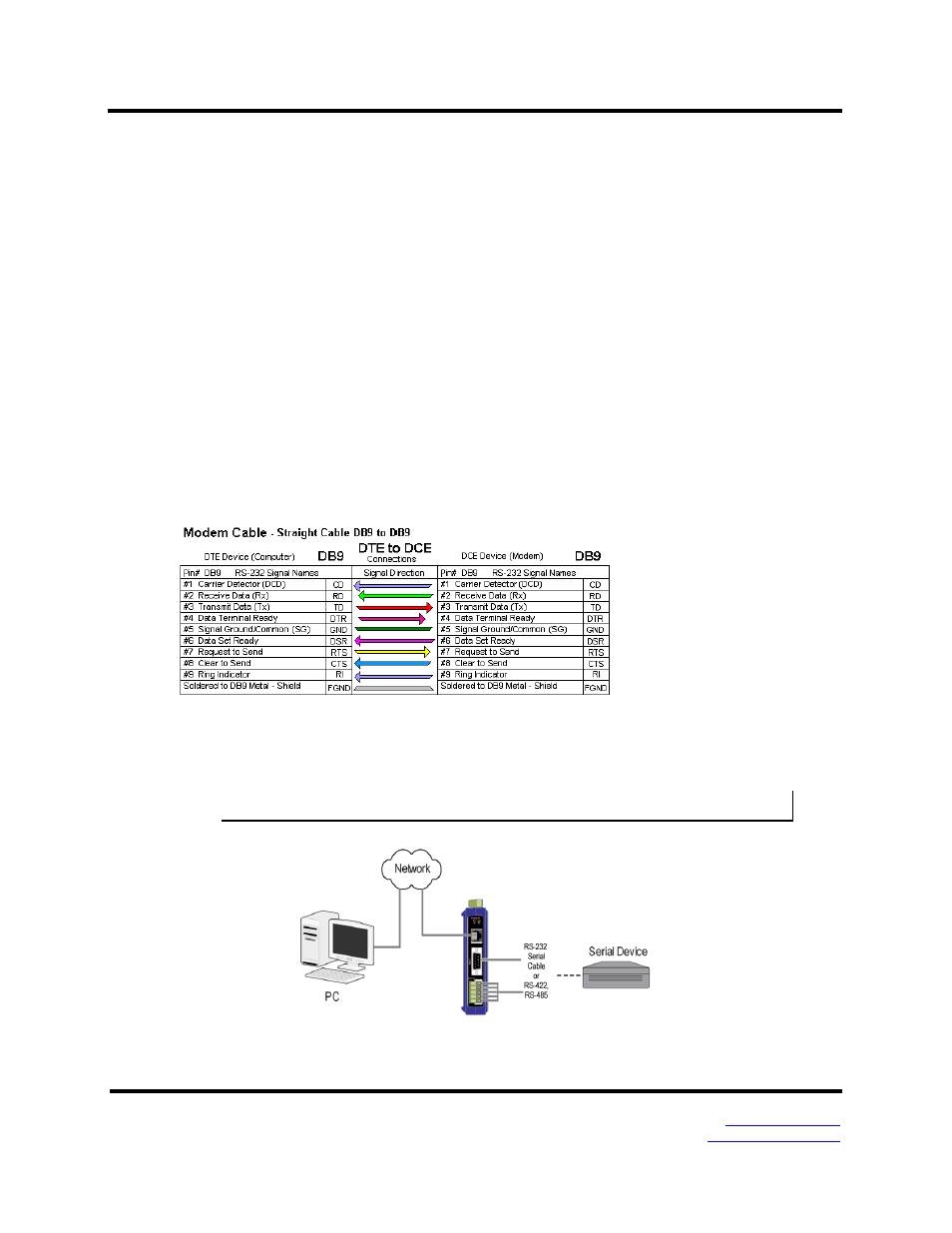
If you select RS-232 mode when you configure the Modbus gateway, you must connect
the Modbus serial network to the Modbus gateway via a serial cable. The MESR901 is a
DTE. If the Modbus network is a DTE, use a null modem (cross-over) cable. If the
Modbus network is a DCE, use a straight-through cable. DTE and DCT ports are
complementary, the Output signals on a DTE port are Inputs to a DCE port, and Output
signals on a DCE port are Inputs to a DTE port. The signal names match each other and
connect pin for pin. Signal flow is in the direction of the arrows. (see figure below)
If you select RS-422 mode, RS-485 2-wire mode, or RS-485 4-wire mode when you
configure the Modbus gateway, you must connect the Modbus network appropriately, via
the 5-position terminal block.
Note: Refer to Appendix D for connector pin out information.
Figure 13. MESR901 Connections