B&B Electronics MESR900 Series - Fiber Models - Manual User Manual
Page 15
3. Setup and Connections
VlinxMESR9xx Modbus Gateway
Page 11
Manual Documentation Number MESR9xx-2113m
www.bb-elec.com/
www.bb-europe.com/
3
3
.
.
M
M
o
o
d
d
b
b
u
u
s
s
G
G
a
a
t
t
e
e
w
w
a
a
y
y
S
S
e
e
t
t
u
u
p
p
a
a
n
n
d
d
C
C
o
o
n
n
n
n
e
e
c
c
t
t
i
i
o
o
n
n
s
s
Note: In this section devices to be connected to the Modbus gateway’s serial connection are simply
referred to as the “Modbus network”.
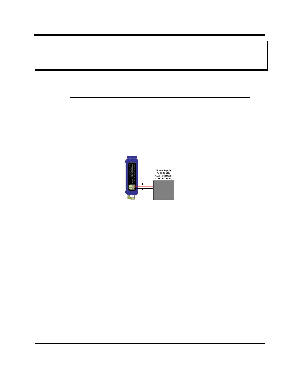
Connecting the Power Supply
Connect a DC power supply to the power terminals on the top of the Modbus gateway.
Polarity of the wires is indicated on the label on the side of the Modbus gateway.
Acceptable voltages are between 10 VDC and 48 VDC. The power supply must be
capable of supplying 4 Watts for MESR90x units or 6 Watts fro MESR92x units.
Figure 12. MESR Power Connection
Connecting MESR9xx Modbus Gateways to Modbus networks
MESR9xx Modbus Gateways can be configured to connect to Modbus networks using
RS-232, RS-422, RS-485 2-wire and RS-485 4-wire.
RS-232 connections support eight signal lines plus Signal Ground. Signals are single
ended and referenced to Ground. Default communications parameters are 9600, 8, N, 1
and no flow control implemented.
RS-422 connections support two signal pairs: RXA(-), RXB(+) and TXA(-), TXB(+),
plus GND. The data lines are differential pairs (A & B) in which the B line is positive
relative to the A line in the idle (mark) state. Ground provides a common mode reference.
RS-485 connections support 2-wire or 4-wire operation.
When configured for 4-wire operation the connection supports two signal pairs: RXA(-),
RXB(+) and TXA(-), TXB(+), plus GND. This makes full-duplex operation possible. The
data lines are differential pairs (A & B) in which the B line is positive relative to the A
line in the idle (mark) state. Ground provides a common mode reference.