B&B Electronics MESP211D_T - Manual User Manual
Page 13
Setup and Connections
Vlinx MESP211 Modbus Gateway
12
lines are differential pairs (A & B) in which the B line is positive relative to the A line in the
idle (mark) state. Ground provides a common mode reference.
When configured for 2-wire operation the connection supports one signal pair: Data B(+)
and Data A(-) signal channels using half-duplex operation. The data lines are differential
with the Data B line positive relative to Data A in the idle (mark) state. Ground provides a
common mode reference.
CONNECTING THE MESP211
The MESP211 has either a DB9M serial connector or a 5-position terminal block connector.
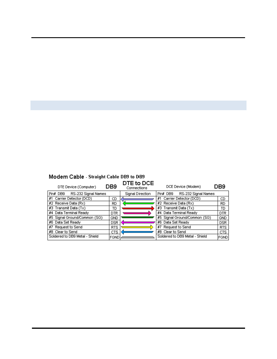
If you select RS-232 mode when you configure the Modbus Gateway, you must connect the
Modbus serial network to the Modbus Gateway via a serial cable. The MESP211 is a DTE. If
the Modbus network is a DTE, use a null modem (cross-over) cable. If the Modbus network
is a DCE, use a straight-through cable. DTE and DCE ports are complementary, the Output
signals on a DTE port are Inputs to a DCE port, and Output signals on a DCE port are
Inputs to a DTE port. The signal names match each other and connect pin for pin. Signal
flow is in the direction of the arrows
MESP211 Serial Connections
Figure 10.