B&B Electronics MESP211D_T - Manual User Manual
Page 12
Setup and Connections
Vlinx MESP211 Modbus Gateway
11
3. SETUP AND CONNECTIONS
Note: In this section devices to be connected to the Modbus Gateway’s serial connection are
simply referred to as the “Modbus network”.
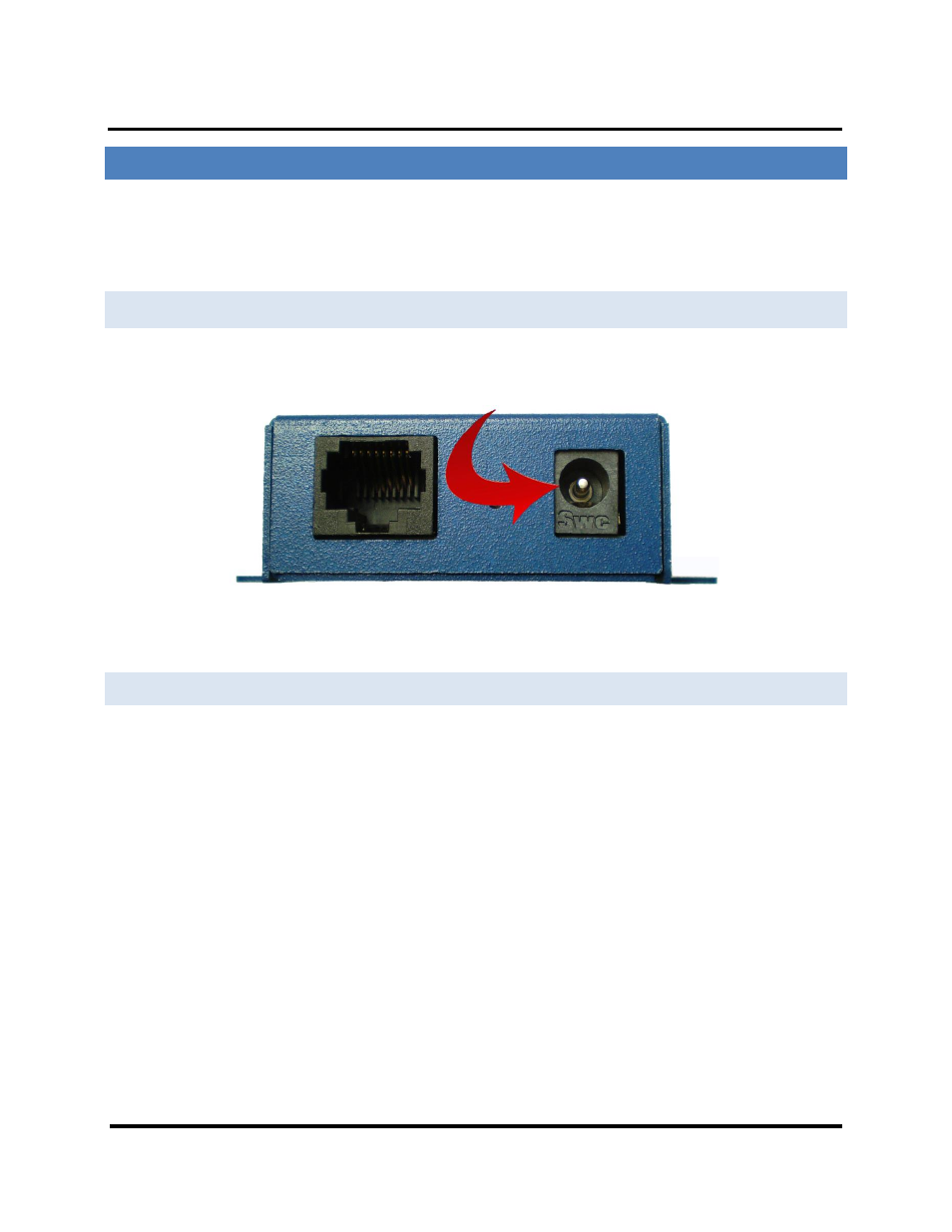
CONNECTING THE POWER SUPPLY
Connect a DC power supply to Modbus Gateway. Acceptable voltages are between 10 VDC
and 30 VDC. The power supply must be capable of supplying 4 watts.
MESP211 Power Connection
Figure 8.
Figure 9.
CONNECTING MESP211 MODBUS GATEWAYS TO MODBUS NETWORKS
MESP211 Modbus Gateways can be configured to connect to Modbus networks using RS-
232, RS-422, RS-485 2-wire or RS-485 4-wire.
For the MESP211D
RS-232 connections support eight signal lines plus Signal Ground. Signals are single ended
and referenced to Ground. Default communications parameters are 9600, 8, N, 1. RS-
422/485 connections are also supported with the DB9 connector.
For the MESP211T
RS-422 4-wire connections support two signal pairs: RXA(-), RXB(+) and TXA(-), TXB(+),
plus GND. The data lines are differential pairs (A & B) in which the B line is positive relative
to the A line in the idle (mark) state. Ground provides a common mode reference. RS-232
connections are also supported with the terminal block connector.
RS-485 connections support 2-wire or 4-wire operation.
When configured for 4-wire operation the connection supports two signal pairs: RXA(-),
RXB(+) and TXA(-), TXB(+), plus GND. This makes full-duplex operation possible. The data